Do you have a question about the YZ Systems NJEX 7300G and is the answer not in the manual?
Guidance on navigating and utilizing the instruction manual effectively.
Contact information and procedures for obtaining technical assistance from YZ Systems.
Explanation of the core components and how the NJEX 7300G system functions.
List and description of optional components and accessories available for the NJEX 7300G system.
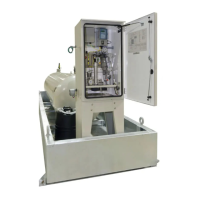
Identification and description of the primary physical components making up the NJEX-7300G system.
Visual representation of the fluid and gas pathways within the NJEX-7300G system.
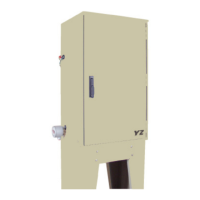
Instructions and guidelines for securely mounting the NJEX-7300G system enclosure.
Details on making the necessary electrical and signal connections for system operation.
Specific mounting procedures for NJEX skid-mounted systems, including dimensional data.
Field connection requirements for NJEX SkidMount systems.
Step-by-step procedure for the initial filling of the bulk odorant storage tank.
Procedure for replenishing the odorant in the bulk storage tank.
Introduction to the control and electronics system of the 7300G, including enclosure and power supply.
Explanation of the N-300 controller keypad functions and dual-use capabilities.
Procedure for safely powering on the NJEX system and navigating initial displays.
Functions of the Test and Standby keys for pump operation and system readiness.
Details on the system's power supply, including solar panels and battery backup.
Methods for communicating with the N-300 controller, including Modbus and Sentry software.
Configuring essential operational parameters like injection rate, pump displacement, and odorant density.
Configuring parameters for time-based operation, including pump displacement and time intervals.
Procedure for calibrating analog flow signals, including zero and span adjustments.
Steps to calibrate the zero reference point for the expansion tank pressure transmitter.
Procedure for calibrating the zero reference point for the odorant inlet pressure transmitter.
Steps for calibrating pulse flow inputs, including setting span frequency.
Understanding the characters and indicators displayed on the N-300 controller screen.
Accessing and interpreting real-time operational data displayed on the N-300 controller.
Monitoring the odorant level within the Verometer and understanding associated alarms.
Display of flow rate and associated alarms, including loss of signal and overflow conditions.
Configuring the enable/disable status for various system alarms like pump, battery, and signal alarms.
Procedures for testing alarm outputs and simulating alarm conditions for verification.
Adjusting the N-300 controller's internal clock for accurate date and time stamping.
Introduction to the mechanical components of the 7300G system.
Description of the odorant inlet manifold and the primary odorant filter assembly.
Explanation of the fill valve's function in controlling odorant flow into the Verometer.
Description of the Verometer's role as an odorant meter and its interaction with the controller.
Details on the NJEX 7000F pump, its operation, and maintenance aspects.
Description of the odorant discharge manifold and its connections.
Information about the NJEX gas filter used for pneumatic supply conditioning.
Description of the solenoid valves and pneumatic relay manifold controlling system operations.
Function and components of the expansion tank, acting as a pressure buffer.
Procedures for setting system pressures and ensuring correct valve positions before startup.
Testing and adjusting the low-pressure relief function of the overflow protector.
Step-by-step guide for initiating the NJEX 7300G system after installation and setup.
Procedure for safely shutting down the NJEX 7300G system during operation.
Recommended schedule for proactive maintenance to ensure system reliability.
List of essential spare parts recommended for maintaining the NJEX system.
Detailed inspection procedure for the overflow protector assembly.
Steps for performing purging operations on the system and expansion tank.
Procedure for safely venting pressure gas, including necessary precautions.
Step-by-step instructions for filling the Verometer with odorant.
Procedure for priming the system and initiating its operation after maintenance.
Guidance on effectively using the troubleshooting section to resolve operational issues.
Recommended chronological approach to resolving NJEX system issues.
Contact information for further technical assistance if issues cannot be resolved.
Crucial safety precautions to be followed during system maintenance and troubleshooting.
Information and troubleshooting steps for alarms related to the odorant tank level.
Steps to diagnose and resolve issues causing the battery low alarm.
Troubleshooting procedures for both signal alarms and non-alarm indicators.
Description and troubleshooting for various alarms related to Verometer performance.
Troubleshooting guides for pump over-pumping, under-pumping, and failure alarms.
Exploded view illustration of the assembled NJEX Model 7000F pump.
Exploded view of the pump's actuation assembly, detailing its components.
Exploded view of the pump's diaphragm cartridge assembly.
Exploded view of the pump's check valve assembly, showing its parts.
Exploded view illustration of the fill valve and its components.
Exploded view of the VM-1100 Verometer, including its filter assembly.
Illustration of the bulk odorant filter and its components.
Illustration of the NJEX gas filter and its parts.
Illustration showing the internal components of the electronics assembly.
Illustration of the SPS-12 solar power supply unit.
Illustration of the LPS-120/240 charger supply unit.
Wiring diagram for the optional heater unit.
Configuration parameters for Modbus communication, including protocol and baud rates.
List of Modbus function codes supported by the N-300 controller.
Details on Boolean data types for status and control using Modbus functions.
Modbus control functions for managing pump, standby, and other system states.
Modbus registers for reading alarm statuses, including latching behavior.
Modbus registers for reading various system statuses like operation mode and alarm enablement.
Data types and functions for reading and writing integer registers for results and parameters.
Modbus registers providing access to system results data like flow rates and dates.
Modbus registers for configuring system parameters, requiring system stop.
List of Modbus exception codes indicating errors during query processing.
Form for recording initial NJEX 7300G system information and parameters.
Standard form for documenting troubleshooting steps and observations for the NJEX system.
Diagram illustrating the N-300 controller display and menu flow.
Electrical wiring diagram for controlling and operating the NJEX system.
Specific connection requirements for ATEX certified NJEX 7300G systems.
| Category | Industrial Equipment |
|---|---|
| Manufacturer | YZ Systems |
| Model | NJEX 7300G |
| Hazardous Area Approval | ATEX, IECEx |
| Type | Guided Wave Radar Level Transmitter |
| Output | 4-20 mA HART |
| Power Supply | 24 VDC |
| Process Connection | 1-1/2" NPT |
| Operating Temperature | -40 to 150 °C |
| Operating Pressure | -1 to 40 bar |
| Accuracy | ± 2 mm |
| Probe Type | Single Rod |
| Housing Material | Aluminum |