Do you have a question about the Zanotti Zer0 120 and is the answer not in the manual?
Details on handling refrigeration oil and avoiding eye contact.
Safety measures for working with high voltage circuits on the unit.
Identifies hazards and levels of awareness for unit operation and maintenance.
Technical specifications for the unit's compressor.
Information on defrost type and initiation settings.
Normal, open, and closed pressures for HP switches.
Approximate refrigerant charge values for R134a and R404a.
Voltage, airflow, and current for condenser fan motors.
Voltage, airflow, and current for evaporator fan motors.
Voltage, ohms, and current for solenoid coils.
Voltage and capacitance values for start and run capacitors.
Lists fuse types, descriptions, and motor voltage/amperage ratings.
Tasks for Maintenance A, including coil cleaning and oil checks.
Tasks for Maintenance B, like replacing brushes and checking fans.
Tasks for Maintenance E, such as checking connections and replacing filter driers.
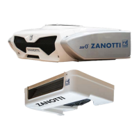
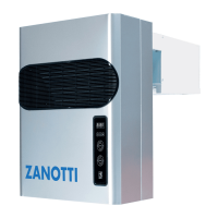
Details the condenser unit's design and components like the coil and filter drier.
Describes the condenser coil's function as a heat exchanger.
Explains the filter drier's role in system cleanliness and moisture removal.
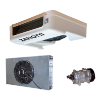
Details the compressor type and its drive mechanism.
Describes the receiver's function as a liquid reservoir.
Explains the high-pressure cut-out switch function.
Describes the compressor pressure regulation valve's function.
How the unit operates during electric standby mode.
Explains the DC motor's role in road mode operation.
Explains the AC motor's role in standby mode operation.
Describes the evaporator assembly, including coil, fans, and expansion valve.
Details the TXV's role in regulating refrigerant flow.
Describes the evaporator coil and its heat absorption process.
Explains the function of the defrost coil under the evaporator pan.
Describes heaters preventing drain tube blockage by ice.
Explains the hot gas solenoid valve's function in heat/defrost modes.
Explains the control system, microprocessor board, and relays.
Details the microprocessor board and its relays.
Describes the components within the control box.
Explains how to interpret the ten-digit model code for unit details.
Details the structure of the 8-character serial number and its components.
Lists safety components and devices that protect the unit from damage.
Explains the operation modes: Cool, Null, Defrost, and Heat.
Details the vapor compression cycle during cooling operations.
Describes the unit's state when the setpoint is reached and no operation occurs.
Explains the process of heating or defrosting using compressed gas.
Provides definitions for symbols used in refrigeration diagrams.
Outlines how a defrost cycle is initiated and operates.
Procedure for initiating a defrost cycle via the in-cab control box.
Function of the defrost relay in controlling the defrost cycle.
Explains the electrical valve controlling hot gas flow to the evaporator.
Describes the normally open valve that directs refrigerant flow.
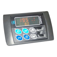
Overview of the microprocessor and in-cab controller.
Explains the interaction between the microprocessor and in-cab controller.
Details the functions controlled by the microprocessor.
Describes the controller's role in user operations and interface.
Procedures for starting the unit in different modes.
Steps for starting in road and standby modes.
Essential checks before vehicle loading to prevent issues.
Checks to perform after the unit has started.
Steps for loading product to minimize frost and heat gain.
Actions to take after loading product into the compartment.
Routine inspections after the unit has completed a trip.
How the unit handles and displays malfunctions.
Method to view recorded alarm codes and messages.
Procedure to clear active and archived alarm messages.
Comprehensive list of alarms, their causes, and remedies.
Overview of regular servicing requirements for unit reliability.
Checks for defrost initiation, thermostat, shutdown circuits, and wiring.
Procedures for checking refrigerant levels and replacing filter driers.
Visual inspection of hoses, leaks, and overall unit integrity.
Safety precautions for connecting gauge sets to the system.
Lists and identifies the parts of a manifold gauge/hose set.
Steps to ready the manifold gauges before connecting to the system.
Procedure for connecting the gauge set to the system's access ports.
Steps for safely disconnecting the gauge set after service.
Procedure for safely evacuating and dehydrating the system.
Method for adding refrigerant charge to the system.
Steps to identify and repair leaks in the refrigeration system.
Process for removing moisture and contaminants from the system.
Procedure for isolating and lowering pressure on the low side.
Methods to inspect refrigerant levels using the sight glass.
How to check for obstructions and replace the filter drier.
Information on removing and testing pressure switches.
Procedures for compressor removal, installation, and oil checks.
Diagnosis and replacement of solenoid coils and valves.
Guidelines for safe and effective brazing techniques.
Information on the TXV and its function in the system.
Steps to check and adjust superheat for proper valve operation.
Troubleshooting expansion valve issues like frosting or poor cooling.
Steps for replacing the expansion valve assembly.
Steps to adjust the Compressor Pressure Regulation valve.
Procedure to test the defrost system's functionality.
Routine inspections for unit integrity and component condition.
Troubleshooting and maintenance for electrical components and circuits.
Common issues affecting desired box temperature and their potential causes.
Table correlating symptoms with possible causes and remedies.
Guide to diagnosing issues based on specific alarm codes and icons.
Table showing pressure-temperature relationships for refrigerants.
Expected pressure readings at specific set points and ambient temperatures.
Overview of common parameter issues and their impact on unit operation.
Details on tS, FuS, IS/SS, and HtP parameters.
Defines abbreviations used in the electrical wiring diagrams.
Safety precautions relevant to electrical maintenance and wiring.
| Brand | Zanotti |
|---|---|
| Model | Zer0 120 |
| Category | Refrigerator |
| Language | English |