Page - 6/18 ADBZP0AB - CAN TILLER - User Manual
the AI1 and AI2 analog inputs take the power supply between PPOT (CNA#9)
and NPOT (CNC#3). The potentiometers related to the AI3 and AI4 analog inputs
take the power supply between PPOT (CNA#9) and NPOT (CNA#12).
The analog devices converted to AI5 and AI6 take the power supply between
PPOT (CAN#9) and NPOT (CAN#12).
The potentiometer supply available are +12 V or +5 V; the maximum load current
provided by the internal voltage regulator is 100 mA so the minimum load is 47 Ω
(PPOT=+5 V), 120 Ω (PPOT=+12 V).
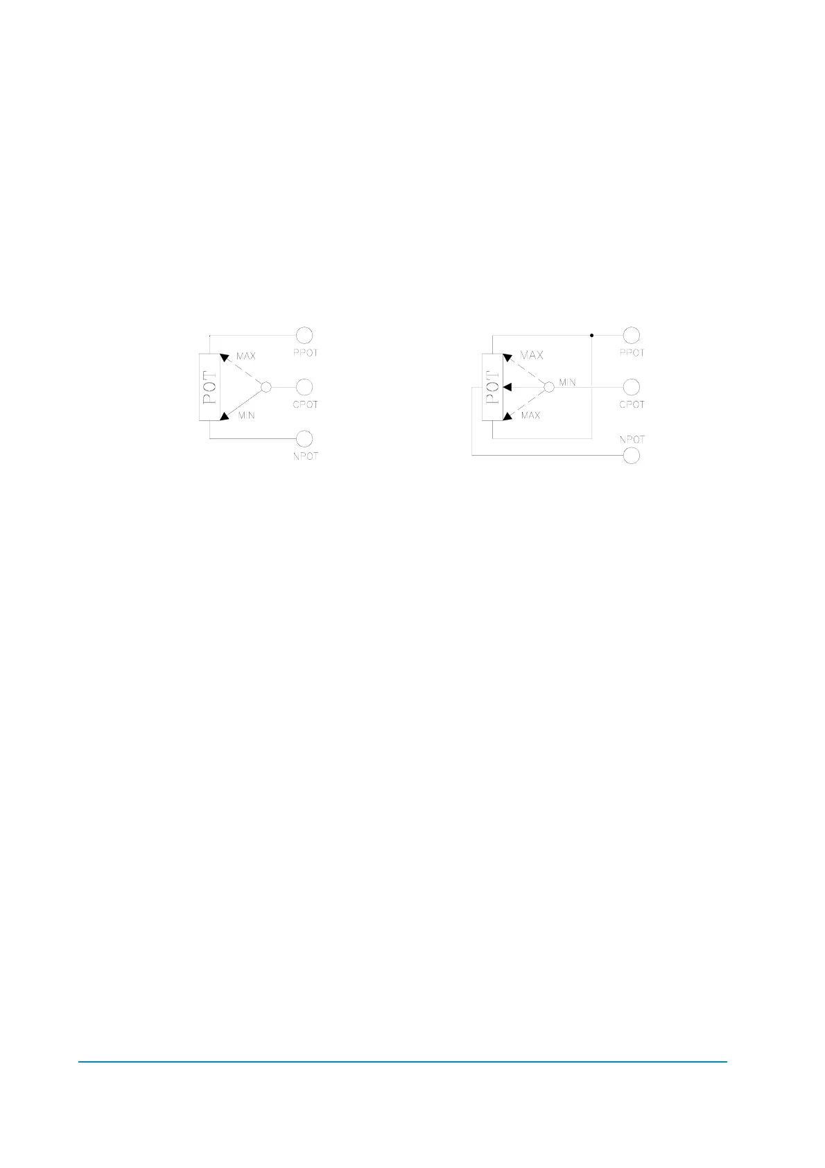
The standard connection of a potentiometer is represented on the left of the
picture below (the potentiometer is at rest in an extreme), together a pair of
switches for the running request. It is possible to use the configuration on the
right (the potentiometer is at rest in the centre), together a pair of switches for the
running request too.