c
d
e
f
g
Height of
secured
CMM assy
incl. pallet
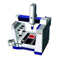
CONTURA G2
X/Y/Z
measuring range
Net weight
of CMM
Max. permissible
workpiece weight
700/700/600 ca. 1280 kg 560 kg
700/1000/600 ca. 1550 kg 730 kg
1000/1200/600 ca. 2310 kg 1150 kg
1000/1600/600 ca. 2810 kg 1500 kg
1000/2100/600 ca. 5171 kg 1814 kg
c
= On-site air supply connection, precleaned compressed air
supply with pressure of 6-10 bar.
d = Power supply ( two outlets with max. 16 A) to be installed
by the customer.
e = Telephone connection (ISDN)
f = CMM compressed air supply connection
g =CMM ↔ control connecting cable
t = Transport height without base
X/Y/Z
measuring range
Length
- a -
Length
- b -
Length
- c -
Length
- t-
700/700/600 1430 1525
920
1603
700/1000/600 1430 1830
1000/1200/600 1743 2030
1225
1000/1600/600 1743 2430
1000/2100/600 1743 2945 1756
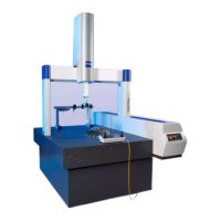
4. CMM Installation Dimensions and Arrangement of Steel Plates
4.1 Installation Dimensions for CONTURA G2 (all dimensions in mm, scale 1:30)
Min. overhead clearance: 200 mm
Controller
Length: ca. 756
Width: ca. 575
Height: ca. 700
T-T = Distance between ta-
ble and bottom of probe
VAST
XT
probe 716
RDS probe 665
Height of
secured CMM
assembly without
pallet and
without Z tower
CONTURA G2
X/Y/Z
measuring range
Max. cable leng.
CMM ↔ control
g
700/700/600 ca. 3700 mm
700/1000/600 ca. 3550 mm
1000/1200/600 ca. 6300 mm
1000/1600/600 ca. 6000 mm
1000/2100/600 ca. 5700 mm
 Loading...