Dimensions
Dimensions 40 / 20 / 10.5 mm
Specications
Supply voltage 9.5 - 22.5 V dc (supplied from DALI)
Control system DALI-2
Supply current 5 mA
Input 2 oating dry contacts
Note: Any switch used shall be LV rated
Output FELV 3.3 V logic level output,
max. current 1 mA
Wiring 0.5 - 0.75 mm
2
Strip 6 - 7 mm
Operating temperature 0 to 45°C
Material PC
Ingress protection IP20
Product range
Order code Description
zc-switch DALI-2 switch module, 2 congurable I/O
Installation
Remove the product from the box and inspect it for any damage. If
you believe the product to be damaged or otherwise unsound, do not
install the product. Please pack it back into its box and return it to the
place of purchase for replacement.
If the product is satisfactory, proceed with the installation:
1 Ensure safety warnings are adhered to.
2 Connect the two DALI terminals to the DALI line ensuring wiring
regulations are followed. DALI is not polarised. DALI is not SELV
and as such must be treated as LV. Do not connect the switch to
any mains voltages.
3 Connect the momentary switch(es) to the oating contact inputs
(A/B). Only connect one momentary switch per input.
Do not connect momentary input to mains voltage.
4 Install switch behind the wall-plate or mounting enclosure for
momentary switch. Note default conguration is A/B input.
Conguration dependant on DALI-2 application controller.
40
20
10.5
System overview
Wallplate
zc-controller
zc-psu
DALI luminaire
zc-relay
Load
Lʼin
Lʼout
L N
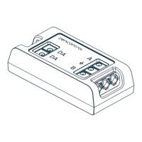
DA DA
N L
L′ out
L′ in
DA DA
Safety information
■ This product must only be installed by a licensed electrician.
■ Before commencing installation turn off and isolate the
electrical supply.
■ There are no user serviceable parts, attempting to service any
part of the product will void the warranty
■ The switch must not be connected to any mains. It is
powered directly from the DALI line.
■ DALI is not SELV and as such should be treated as LV.
■ As the installer, it is your responsibility to ensure you comply
to all relevant building and safety codes. Refer to application
standards for the relevant rules.
■ When the installation is complete, leave this manual with the
building’s owner for future reference.
■ The installer must protect against accidental contact, all
terminals are not safe to touch.
■ There is no isolation between the control terminals and
supply. Outputs should be treated as LV.
Wiring diagram
COM
Switch
LED
A
B
COM
Switch
Switch
A
B
A
B
Input conguration (default)
Input / output conguration
Wire preparation
6 - 7 mm
0.5 - 0.75 mm
2
DALI-2 switch module zc-switch