Do you have a question about the Zenith MC7051 and is the answer not in the manual?
Essential safety checks and guidelines for servicing audio equipment to prevent hazards.
Details on cabinet, chassis, speaker, and other features for various receiver models.
Detailed specifications for various record changers, including part numbers and features.
Features and specifications for various tape units, including part numbers and operational notes.
Introduction to service information for MC7031, MC7041, MC7051 models.
Comparison of power output, controls, switches, and connectors across MC7031, MC7041, MC7051.
Explanation of component identification on circuit boards and block diagram usage.
Details on replacing the power output IC and operating precautions.
Guidelines for aligning AM, FM, and Multiplex sections and necessary equipment.
Procedure for adjusting audio output idle current under no signal conditions.
Step-by-step procedure for AM IF alignment using a sweep generator.
Steps for AM IF alignment using a sweep generator for MC7051.
Procedure for FM IF and Detector alignment for the MC7051 model.
Steps for accessing the chassis by removing cabinet top and bottom covers.
Instructions for removing the front panel to access front-edge components.
Explanation of the FM RF stage, including components and their function.
Explanation of the circuit designed to protect speakers from excessive voltage or current.
Block diagrams for ICs like IC901, IC951, IC201, IC301 in MC7031/MC7041.
Block diagrams for ICs like IC101, IC201 in MC7051, showing signal flow.
Foil side views of chassis wiring and components for MC7051 sections.
Foil side view of chassis wiring for MC7031 controls and switches.
Overall schematic diagram for the MC7031 model, showing all circuits and connections.
Schematic for the RF, IF, MPX, and Phono preamp sections of the MC7041.
Schematic for the power supply section of the MC7041 model.
Foil side view of MC7051 power supply and phono preamp chassis wiring.
Foil side view of MC7051 audio output and speaker protection chassis wiring.
Overall chassis layout diagram for the MC7051 model, showing component locations.
Exploded view of the MC7031 model, illustrating assembly and component placement.
Exploded view of the MC7041 model, showing assembly and component arrangement.
Exploded view of the MC7051 model, illustrating assembly and part placement.
| Brand | Zenith |
|---|---|
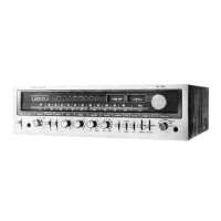
| Model | MC7051 |
| Category | Stereo Receiver |
| Language | English |