Page A-16
MOUNTING AND INSTALLATION:
Select the desired mounting locations and drill screw and cable holes as indi-
cated on the template diagram. Refer to the Dimensions Diag ram on the next
page.
Run cable/harnesses between Processor and Control Head. Label both ends
with the Station it connects
(EXAMPLE: Port, Cen ter, or Starboard; Port Thrust, Port
Throttle; etc.)
There are two types of Control Head connections available: Plug or Terminal
Connect ed. Bo th types ma y be used w ith MicroComma nder , Clea rComma nd, or
CruiseComma nd using the ap propriat e ca ble o r harness. Follow the a ppropria te
steps for the Control Head that has been supplied for your system.
Standard Cable
Remove the six screws holding the bottom cover of the
Control Head housings and set aside.
Insert cable t hrough the correct cable grip in the bottom
cover.
Strip back the PVC cover on the shielded cable approxi-
mately 2-1/2"
(63,5mm)
at the Control Head.
At the Control Head end of the cable strip and cut off the
shielding and drain wire flush with the end of the PVC
cover (the drain wire at the Control Head is not connected
to ground).
Strip 3/8"
(9,5mm)
insulation off each wire.
Twist the individual strands of the wires to minimize fray-
ing.
Crimp a locking fork terminal (inclu ded w ith ea ch Control
Head) to eac h of th e conductors.
Make connections to the Control Head as indicated in the
following TERMINAL CONNECTIONS diagrams.
Pluggable
Plug Control Head cable
into the pigtail at the
Control Head.
(Ensure the
correct Processor Cable is
being plugged into the corre-
sponding Control Head lever
pigtail)
.
When connecting the
plugs, ensure that the
release button or but-
tons are depressed and
held until plug is fully
connected or discon-
nected. Connecting or
disconnecting plugs
without depressing and
holding th e re l eas e but-
ton or buttons will dam-
age the plug.
ALWAYS REFER TO THE MANUAL THAT IS
SUPPLIED WITH THE CONTROL SYSTEM
FOR ANY UNIQUE CONTROL HEAD CON-
NECTIONS FOR YOUR SYSTEM.
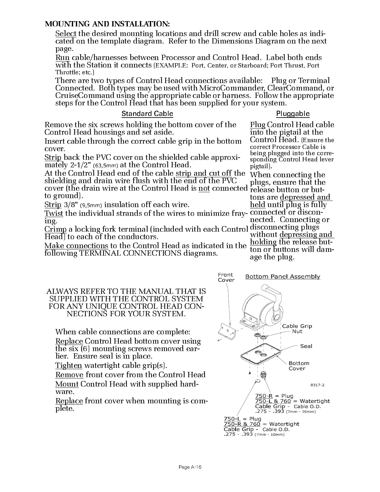
When cable connections are complete:
Replace Control Head botto m cove r using
the six (6) mounting screws removed ear-
li er. Ens ur e seal is in pl ace.
Tighten watertight cable grip(s).
Remove front cover from the Control Head
Mount Control Head with supplied hard -
ware.
Replace front cover when mounting is com-
plete.

 Loading...