5.2.2 Motor cable
The screening of the motor cables (U1, V1, W1, PE) must be two-fold (both ends), i.e. connected to
the protective conductor at the controller and at the motor.
The use of a screened motor cable of max. 10 m in length will ensure compliance with the limiting
value class B in accordance with EN 55011.
The screening of the thermostats “TB” or thermistor “TP” connection cable for motor protection may
only be connected to the protective conductor at one end at the controller. Because of possible
coupling unbalances they may not be routed in the same cable harness as the motor cables.
5.2.3 Control cables
Pay attention to sufficient distance from powerlines and motor wires to prevent interferences. The
control cable may not be longer than 30 m. Screened control cables must be used when the cable
length is longer than 20 m. When using a shielded cable connect the shielding to one side only, i.e.
only to the control unit with the protective ground (keep cable short and with as little inductance as
possible!).
5.2.4 Harmonics current for devices ≤ 16 A
According to EN 61000-3-2 these devices are to be classified as “professional” devices.
Connection to a low voltage supply (public networks) is allowed insofar as this has been clarified with
the respective energy supply company responsible.
5.2.5 Harmonics current and line impedance for devices > 16 A and ≤ 75 A
Extract from EN 61000-3-12, valid for equipments with rated current > 16 A and ≤ 75 A, connected to
public low-voltage systems.
This equipment complies with IEC 61000-3-12 provided that the short-circuit power S
SC
is greater than or equal
to R
SCE
x S
equ
at the interface point between the user's supply and the public system.
It is the responsibility of the installer or user of the equipment to ensure, by consultation with the distribution
network operator if necessary, that the equipment is connected only to a supply with a short-circuit power S
SC
greater than or equal to R
SCE
x S
equ
.
S
SC
Short-circuit power from line at the interface point between the user's supply and the public system
S
equ
Rated - apparent power for three phase devices: S
equ
= √ 3 x U
I
x I
equ
(U
I
= phase to phase voltage
Technical data “Line voltage”)
(I
equ
= rated current of the device
Technical data “Rated current input”)
R
SCE
Short-circuit ratio
For this devices: R
SCE
≥ 120
5.3 Mains connection
5.3.1 Line voltage
Power from the mains is connected to terminals: PE, L1, L2, L3. Here, it must be strictly observed that
the mains voltage lies within the allowable tolerance specifications (
Technical data and nameplate
affixed to the side).
Danger due to electric current
Not suitable for IT system!
5.3.2 Required quality attributes for the mains voltage
Danger due to electric current
The mains voltage must comply with the EN 50160 quality characteristics and the defined standard
voltages in IEC 60038!
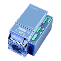
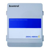
Operating Instructions Icontrol Basic – model series FSDM2.6...62 Electrical installation
L-BAL-E160-GB 1701 Index 004 Part.-No.
12/28
 Loading...