Do you have a question about the ZIEHL-ABEGG NETcon A-G-102ANE and is the answer not in the manual?
| Manufacturer | ZIEHL-ABEGG |
|---|---|
| Protection Class | IP20 |
| Category | Control Panel |
| Product Type | Network Controller |
| Model | A-G-102ANE |
| Communication Protocol | BACnet IP |
| Supply Voltage | 24 VDC |
| Housing Material | Plastic |
Outlines the manual's organization and purpose for correct system use.
Identifies intended users with planning, installation, and maintenance qualifications.
States limitations of manufacturer liability for errors, misuse, or unauthorized modifications.
Details copyright protection and restrictions on reproduction, translation, or data medium transfer.
Specifies that the equipment must be used solely for confirmed purposes agreed upon by contract.
Describes warning symbols and their hazard levels, depicted according to the degree of risk.
Emphasizes using the device and accessories in flawless condition per instructions to prevent defects.
Defines qualifications, knowledge of regulations, and supervision needed for personnel working with the device.
Highlights safety measures during commissioning and operation, including fuse replacement and cabinet closure.
Details safety protocols for working on electrical components, ensuring isolation, and checking live parts.
Prohibits unauthorized modifications and mandates use of genuine ZIEHL-ABEGG spare parts for safety.
Outlines owner responsibilities for safe operation, maintenance, instruction availability, and personnel training.
Stresses informing external staff about hazards and monitoring their work methods to prevent incidents.
Describes the device's use with MODBUS fans/FFUs for networked systems up to 63 units.
Provides instructions for safe packing, handling, and transport, including avoiding shocks and using original packaging.
Specifies storing the device in its original packaging in a dry, weather-proof room, avoiding extreme temperatures.
Mandates professional and environmentally friendly disposal of the device according to national regulations.
Details compliance points for mechanical installation to prevent defects from assembly errors or environmental influences.
Advises storing the controller at room temperature to avoid condensation and potential functional faults.
Lists mandatory safety rules and precautions for electrical work, including personnel qualifications and isolation measures.
Guides on spacing and shielding control lines for interference avoidance, specifying maximum lengths and connection methods.
Specifies connection terminals (V+in, V-in) and allowable supply voltage tolerances for the device.
Describes the function of digital inputs D1 for day/night switchover and D2 for stop/start control.
Explains the function and connection of the built-in potential-free alarm relay for external fault indication.
Details the RS-485 interface for MODBUS networking, including connection points and fail-safe circuit.
Covers correct wiring, recommended cables, network design, and default interface settings for RS-485 networks.
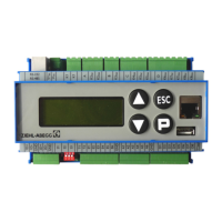
Describes the device's user interface, including the 4-line LCD display and the functions of the four control buttons.
Provides an initial view of the NETcon's menu navigation, including system status display and key press behavior.
Illustrates the menu flow for navigating and accessing fan information, error history, PIN editing, and fan settings.
Continues the graphical representation of menu navigation for fan settings, addressing, and internal parameters.
Further details the menu navigation path for broadcast settings, fan addressing, and internal configuration options.
Explains how to navigate menus, select parameters, and adjust values using the device's arrow keys and P/ESC buttons.
Details the process of setting fan parameters like speed and saving changes, noting incremental adjustments.
Lists essential checks and conditions before initiating device commissioning, including connections and supply voltage.
Guides through the automatic fan addressing process, starting from the main menu and selecting auto-addressing.
Explains completing auto-addressing, displaying results, and applying broadcast settings to all fans.
Presents methods for connecting fans, emphasizing the GND connection for auto-addressing and detailing wiring schemes.
Illustrates the wiring for a standard MODBUS connection between the NETcon and multiple fans using terminals.
Shows the RJ45 wiring setup using the ECblue connection box for networking, simplifying fan connections.
Describes the FAN INFO menu, which displays real-time fan data such as speed, set values, and operating status.
Details the ERROR menu for viewing and acknowledging system faults, including fault type, affected fan, and timestamp.
Explains the PIN input function to prevent unauthorized parameter changes and outlines PIN behavior on resets or errors.
Covers settings for individual fans, allowing adjustment of speed parameters (SetIntern1/2) and fan ON/OFF control.
Details specific settings within FAN SET, including speed adjustments, ON/OFF control, and communication parameter reloading.
Allows applying common settings like speed or ON/OFF status to all connected fans simultaneously via broadcast commands.
Manages fan addressing, enabling automatic or manual assignment of device IDs for network configuration.
Allows setting the NETcon's device name, date/time, and clearing the error list for system management.
Enables or disables the alarm relay function for specific operational needs, such as during revision work.
Activates the digital input D2 for using the Stop/Start function, essential for controlling fan operation.
Lists key specifications including voltage supply, interfaces, inputs/outputs, temperature, and housing protection.
Provides a visual schematic of electrical connections for power supply, MODBUS, digital inputs, and the alarm relay.
Shows the physical dimensions of the NETcon device, including length, width, and depth, in millimeters.
Provides contact information for ZIEHL-ABEGG SE, including address, phone number, email, and website.
Offers contact details for technical support regarding commissioning, malfunctions, and general inquiries.
