1. The Caravan/Boat Battery
If the manufacturer, or your dealer, has not fitted a battery; we recommend that
one is fitted in order to get the best out of your ZIG electrical system. Most
manufacturers allocate a space for the battery and supply the necessary cable for
connection. In this case, simply locate a new battery in the space provided and
connect the wires to the battery; red to positive, black to negative. The 25 amp line
fuse (supplied) should be connected in the positive lead. Note that if blue and
white wires are used blue is positive, white is negative. It is important
l/)
that a
proper connection is made to the battery using terminals and screws. Crocodile
clips must never be used; they deteriorate quickly and are a fire risk. A smear of
petroleum jelly should be applied to the battery terminals. See No.4 in "Important
Notes", regarding batteries. If the manufacturer has not allocated a space for the
battery, refer to "Fitting the battery" in "INSTRUCTIONS FOR FITTING".
2. Using your 12 volt equipment
Turn on the "12 volt switch·" and set the "TOURING/ON-SITE·" switch to "ON-
SITE" (down position). The battery condition indicator will light either red or green,
depending on the state of battery, and the 12 volt equipment in the caravan will be
operative. This switch need only be turned off when the caravan is not in use.
Note: that the fridge is independently wired and is not controlled by this switch.
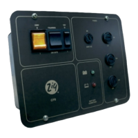
Please read these instructions carefully before operating the electrical
equipment in your caravan. An asterisk* denotes reference to Figure 1.
Figure 1:
The C.F.8 Control Panel
1
MAINS ON / OFF
TOURING / ON SITE 12 VOLT SWITCH
MAINS FUSEHOLDER
BATTERY CONDITION MONITOR
12 VOLT
FUSEHOLDERS
 Loading...