Do you have a question about the Zimmer A.T.S. 1200 and is the answer not in the manual?
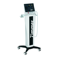
Technical specifications for the A.T.S. 1200 Tourniquet System.
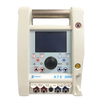
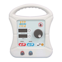
Description of the unit's buttons and rotary knob for operation.
Explanation of the green LED indicator for AC power.
Explanation of the orange LED indicator for battery status.
Details on unit size and the PRESSURE/TIME displays.
Information on UL classification, safety, and EMC compliance.
Describes the purpose and applications of the tourniquet system.
Lists medical conditions where use of the tourniquet is not advised.
Outlines important safety measures and warnings for operating the unit.
Further safety measures and warnings for proper tourniquet application.
Details potential negative outcomes and side effects of tourniquet use.
Guidance on inspecting the unit upon receipt for damage.
Identifies and describes the unit's various controls and connections.
Continues the description of unit controls, indicators, and connections.
Instructions for initial setup, including charging and power connection.
Procedures for verifying unit functionality and calibration status.
Completes the functional and calibration check procedures.
How to set default pressure and time limits for the unit.
Details on setting default pressure and time limits.
Step-by-step guide for operating the unit with a single cuff.
Completes instructions for single cuff operation.
Instructions for operating the unit with two cuffs simultaneously.
Specific procedures for Bier Block anesthesia using the unit.
Lists and explains all possible alarm conditions and their meanings.
Overview of recommended maintenance practices for the unit.
Instructions on how to access internal components for servicing.
Guidelines for routine inspection and cleaning of the unit.
Detailed procedure for calibrating the unit's pressure transducers.
Procedure for checking the system for significant leaks.
Information on checking battery voltage and service recommendations.
Completes the leak testing procedure.
Further details on battery service and replacement.
Guidance on handling unexpected failures and error messages.
Procedures for addressing unscheduled maintenance issues.
A guide to identify and resolve common malfunctions.
Reference values for test points used in troubleshooting.
List of field-replaceable parts with part numbers.
Environmental conditions for unit storage and transportation.
Step-by-step guide to opening the unit's front case.
Guide to carefully sliding the front case off.
Instructions for safely disconnecting internal wiring.
Steps to remove the unit's rear case.
Visual guide to separating the rear case for component access.
Diagram showing the layout of components on the control board.
Explains safety warnings, cautions, and standard symbols used in the manual.
Important attention and caution notices regarding unit operation.
Warnings about explosion hazards and electric shock risks.
Warning regarding the correct replacement of the battery fuse.
Contains the electrical schematics for the A.T.S. 1200 Tourniquet System.
| Brand | Zimmer |
|---|---|
| Model | A.T.S. 1200 |
| Category | Medical Equipment |
| Language | English |