Page 34 MS - SOUND decoders MS440 to MS990 and MN - NON-SOUND decoders MN170 to MN340
ZIMO small-scale decoders have between 4 and 12 function outputs (FO). Consumers connected to
these outputs (lights, smoke generator etc.) are switched ON and OFF with the function keys on the
controller. Which function key controls which function output can be defined with the NMRA function
mapping.
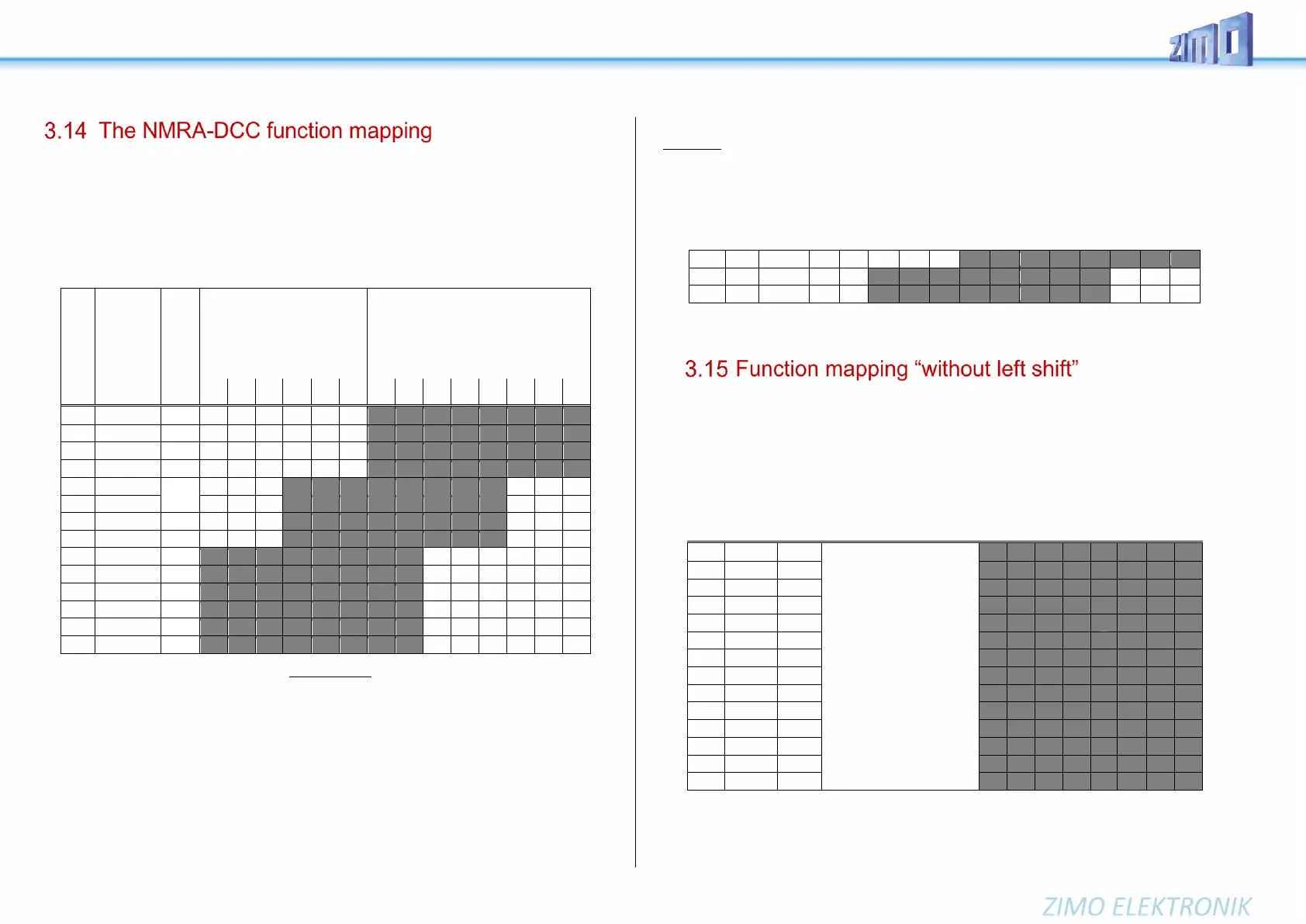
CVs #33 to #46
define the NMRA function mapping. Unfortunately, this function mapping also has its limitations (only
one 8-bit register is available for each function, which leaves only 8 outputs to select from) and only the
headlight function is intended to change with direction.
Function key
on the controller
Numeric key
on the
ZIMO
Controller
The black dots in the table above indicate the default settings at the time of delivery, where each function
key corresponds to the same numbered function output. Therefore, the following values were written
into these CVs by default:
CV #33 = 1
CV #34 = 2
CV #35 = 4
CV #36 = 8
CV #37 = 2
CV #38 = 4
CV #39 = 8
CV #40 = 16
CV #41 = 4
and so on..
EXAMPLE of a modification to the function mapping: The F2 key (ZIMO #3 key) should switch output
FO4 in addition to output FO2. Moreover, F3 and F4 should NOT switch FO3 and FO4 but rather FO7
and FO8 (couplers, for example). New values are to be entered into the relevant configuration variables
as follows:
CV #36=40
CV #37 = 32
CV #38 = 64
By
CV #61 = 97
the left shift of higher CVs (#37 and up, according to the original NMRA function mapping) is deactivated,
which allows higher function keys to be mapped with lower function outputs: e.g.: “F4 controls FO1” is
not possible with NMRA, but is with ZIMO.
FO6 FO5 FO4 FO3 FO2 FO1 Headlights
rear front
7
6
5
7
6
5
7
6
5
7
6
5
4
3
2
6
5
4
3 ⚫
2
7
6
5
4⚫
3