MS - SOUND decoders MS440 to MS990 and MN - NON-SOUND decoders MN170 to MN340 Page 39
Low/high beam mask with the low beam mask
One of the function keys F6 (CV #119) or F7 (CV #120) can be defined as a low beam key. Selected
function outputs can be dimmed as required with the function turned ON or OFF (inverted action with Bit
7).
Low beam mask for F6
=
Allocation of
Function outputs
as (for example)
low/high beam
ATTENTION:
Certain settings in CV
#154 (Special output
configurations
for OEM projects)
the meaning of the fol-
lowing CVs changes:
#119, #120,
i.e. those are not low
beam mask anymore.
Selected outputs will dim, according to the dim value
in CV #60, when the F6 key is actuated.
Typical application: Low/high beam
Bit 0 - front headlights
Bit 1 - rear headlights
Bit 2 - function output FO1,
Bit 3 - function output FO2,
Bit 4 - function output FO3,
Bit 5 - function output FO4,
Bit 6 - function output FO5.
Respective Bit = 0: Output will not be dimmed,
Respective Bit = 1: Output will be dimmed with F6
to value defined in CV #60.
Bit 7 = 0: “normal“ effect of F6.
= 1: Inverted effect of F6.
EXAMPLE:
CV #119 = 131: Headlights shall be switched between
high and low beam with F6 (F6 = 1).
Same as CV #119 but with F7 as low beam key.
A “second dim value” with the help of the uncoupler CV
If more function outputs need to be dimmed than CV #60 allows or if some function outputs require a
different voltage and the uncoupler function is not needed on the same vehicle, then
CV #115
can be used as alternative dimming configuration. The respective function outputs must be defined as
“uncoupler output” in the corresponding
CVs #127 - #132, #159, #160
(see “Special effects for function outputs”).
(Uncoupler control
Activation time)
or
“Second dimming value“
Valid, if the effect “ncoupling” is configured in Cvs
#127 - #132, #159, #160.
Tens digit = 0: when used for dimming applications
Ones digit (0 to 9): PWM reduction
(0 to 90 %)
Effects
on FO1, FO2
FO3, FO4, FO5, FO6
on FO7, FO8
= 48 when used to dim
#127 → FO1 #128 → FO2
#129 → FO3 #130 → FO4
#131 → FO5 #132 → FO6
#159 → FO7 #160 → FO8
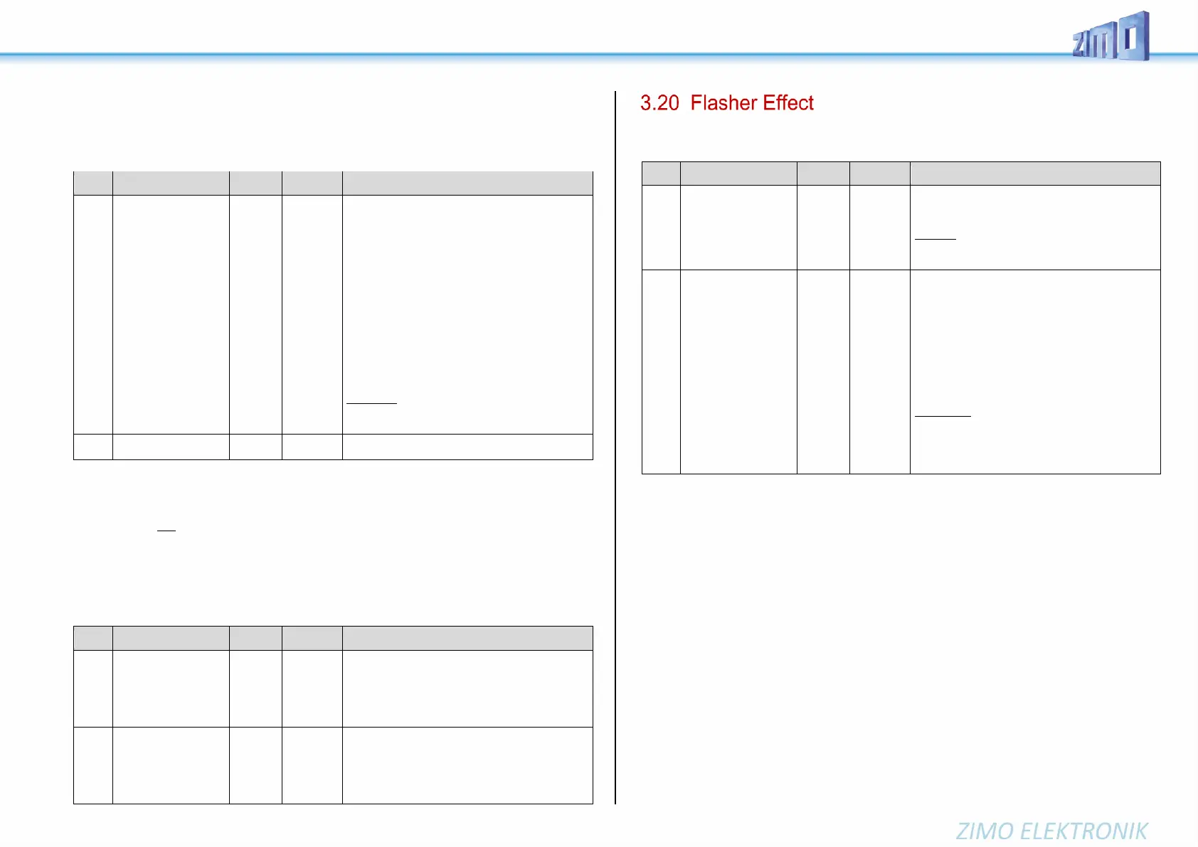
Flashing is actually a lighting effect just like all the others that are summarized in the CVs starting with
#125; for historical reasons though they are listed with their own CVs #117 and #118.
Flasher functions
Outputs are assigned in
CV #118.
Flashing mask
Duty cycle for flasher function:
Tens digit: Off / Ones digit: On
(0 = 100msec, 1 = 200msec…..9 = 1 sec)
Example:
CV #117 = 55: Flashes evenly at 1 a second interval.
i.e. identical on and off times
Flashing mask
=
Allocation of
Function outputs
to the flashing rhythm
CV #117
Selected function outputs will flash when turned ON.
Bit 0 - front headlights
Bit 1 - rear headlights
Bit 2 - for function output FO1, Bit 3 - ...FO2
Bit 4 - for function output FO3, Bit 5 - ...FO4
Respective Bit = 0: No flasher
Respective Bit = 1: Output flashes when turned ON.
Bit 6 = 1: FO2 flashes inverse
Bit 7 = 1: FO4 flashes inverse
(for alternate flashing, i.e. wig-wag)
EXAMPLES:
CV #118 = 12: Function outputs FO1 and FO2 are
assigned for flashing lights.
CV #118 = 168: Outputs FO2 and FO4 shall
flash alternatively, if both are turned on