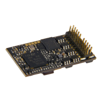
Page 52 MS - SOUND decoders MS440 to MS990 and MN - NON-SOUND decoders MN170 to MN340
Switch input sounds - Volume adjustments:
Planned in SW version 5.00 and later!
Volume setting for the sound activated with switch input S1
= 0: full volume, original sound sample volume (same as 255)
= 1 - 254: reduced volume 1 – 99.5 %
= 255: full volume
Volume setting for the sound activated with switch input S2
Volume setting for the sound activated with switch input S3
Number of sound sample for input S4
Volume setting for the sound activated with switch input S4
Random sounds - Volume adjustments:
Volume setting for sound activated by random generator Z1
Volume setting for sound activated by random generator Z2
Volume setting for sound activated by random generator Z3
Volume setting for sound activated by random generator Z4
Volume setting for sound activated by random generator Z5
Volume setting for sound activated by random generator Z6
Volume setting for sound activated by random generator Z7
Volume setting for sound activated by random generator Z8
Connection between sounds and function output:
(“Connection” means: in the time another sound is played back, a special function output shall be ac-
tivated; typical use: automatic flickering of fire chamber during coal shoveling).
Sound number for connection 1 (usually defined by sound
project and should not be changed if possible). Within the
documentation of (most of the) sound projects sound num-
bers are listed.
Function output to connection 1 which shall be activated - if
the sound is played back. 1 = FO0f, 2 = FO0r, 3 = FO1, ...
Sound number to connection 2
Function output to connection 2:
1 = FO0f, 2 = FO0r, 3 = FO1, ...
Soundnumber to connection 6.
Function output to connection 6:
1 = FO0f, 2 = FO0r, 3 = FO1, ...
See chapter 5.3 SOUND: Basic settings inde-
pendent of powertrain
Chuff sound fre-
quency
according to
“virtual
Cam sensor“
also see
CV #354
in this table
(Steam chuff
frequency
at speed step 5)
CV #267 is only active if CV #268 = 0:
Chuff beats follow the “virtual cam sensor”; an ac-
tual cam sensor is not needed in this case.
The basic configuration “70” results in about 4 to 6
to 8 chuffs per rotation, depending on the selected
chuff-set. Because it also depends in large part on
the motor and gearbox used, an individual adjust-
ment is necessary in most cases in order to
achieve the exact chuff frequency; therefore, CV
#267 is used:
The lower the value the higher the chuff frequency
and vice versa. The setting should be performed at
low speed (around speed step 20-25, not 5).
By means of CV #393 bit 6 = 1 the chuff interval of
CV #267 can be extended 4 times.
Switch to real
cam sensor
and
Number of spikes of
the cam sensor for
chuff beat
and
Special functions
“simple articulated”
steam locos
= 0: “Virtual“ cam sensor is active (to be adjusted
with CV #267, see above).
= 1: = 1: Real cam sensor (connected to „In2”
resp. “In3“ of the decoder) is active, each negative
spike results in a chuff
= 2, 3, 4 … real cam sensor, several triggers in
sequence (2, 3, … 63) result in one chuff beat.
= 128 (bit 7=1 with “virtual” cam sensor): second
driver is a bit slower; only meaningful if a sec-
ond sound sample is available in the sound
project.
= 192 (bits 6 and 7 = 1): When no separate sound
sample is available for the second driver, the
same sample is played back for the second
driver, only a bit slower.
Bit 7 = 1: with real cam sensor, see values above
Cam sensor for driver 1 at IN3 (as always),
Cam sensor for driver 2 at IN2, (only possible
if decóder has two inputs)
A typical sound signature of a passing steam en-
gine is that one chuff out of a group of 4 or 6 chuffs
is louder in volume than the rest; this effect is al-
ready part of the chuff set but can be further ampli-
fied with the help of CV #269.
Fast driving
overlapping effect at
high speed-
effects
0 - 255
(Useful
up to
@ 30)
The individual steam chuffs of a real engine overlap
each other at high speed. Because the frequency
of the chuffs increases but will not shorten to the
same extend, they will eventually blend in to a
weakly modulated swoosh. This is not always de-
sired in model railroading because it does not
sound that attractive, hence CV #271, with which
an adjustment is possible to have the chuff beats
accentuated at high speed or rather fade away.
Opening the cylinder valves on a prototype steam
engine for the purpose of water drainage is entirely
NOTE: The CV immediately ahead of the CVs listed (#740, #742) contains the sound sample
numbers to be played.
NOTE: The CV immediately ahead of the CVs listed (#744, #747 etc.) contain the sound sample
numbers to be played. Possibility to adjust via ZCS (ZIMO CV Setting) tool.
 Loading...