MS - SOUND decoders MS440 to MS990 and MN - NON-SOUND decoders MN170 to MN340 Page 63
7805
1N4007
10 uF,
5 V0
100 uF,
V10
5 V
0 V
Servo 1
Steuerleitung
Servo
10 Fn
Drossel,
z.B. 47uH
MASSE
( 0 V)
PLUS
Program mierpads,
Kontakt ierung verbot en !
Servo 2 Servo 1
Connecting an electric (un)coupler (System “Krois”):
In order to prevent damage to the delicate core of an uncoupler from continuous power, appropriate
adjustments can be made with special CVs for one or several function outputs. To define any output to
an uncoupler output:
First, write the value “48” to the special effect CVs for the outputs an uncoupler is connected to (e.g.,
CV #127 for output #1, CV #128 for output #2 etc.).
Next define a limit for the uncoupler’s activation time in CV #115 (see CV-table):
With the “Krois couplers”, it is recommended to use a value of “60”, “70” or “80” for CV #115; this
means that the pull-in voltage (full track voltage) is limited to 2, 3 or 4 seconds. A reduced “hold” voltage
is not required for Krois, that is why the ones digit is left at 0. Other brand couplers may need
a reduced hold voltage though, like the ones from ROCO for example.
For automatic loco disengaging or automatic coupler unloading and loco disengaging ("coupler
waltz") see CV #116 and chapter Configuration of Electric Uncouplers
Connecting one or several servos to:
“Small” decoder (for H0, TT, N):
The two "SUSI pins" on the decoder can
be switched to operate servos; see chap-
ter "3.24 SUSI pins: switchable to SUSI
or I²C interface, logic level
inputs and outputs or servo
control lines....", CVs #181, #182,
...). Connect the servo’s control wires to
the SUSI pins.
Power for the servos (5 - 6 V) must come
from an external power supply for the
"small" decoders (for H0, TT, N) (see cir-
cuit with 5 V voltage regulator in the picture
on the right).
Large-scale decoder (0, G, 1, ...):
These decoders have their own dedicated
servo connections and a built-in power
supply (therefore no need to switch the
SUSI outputs for servo control, and no ex-
ternal supply is required).
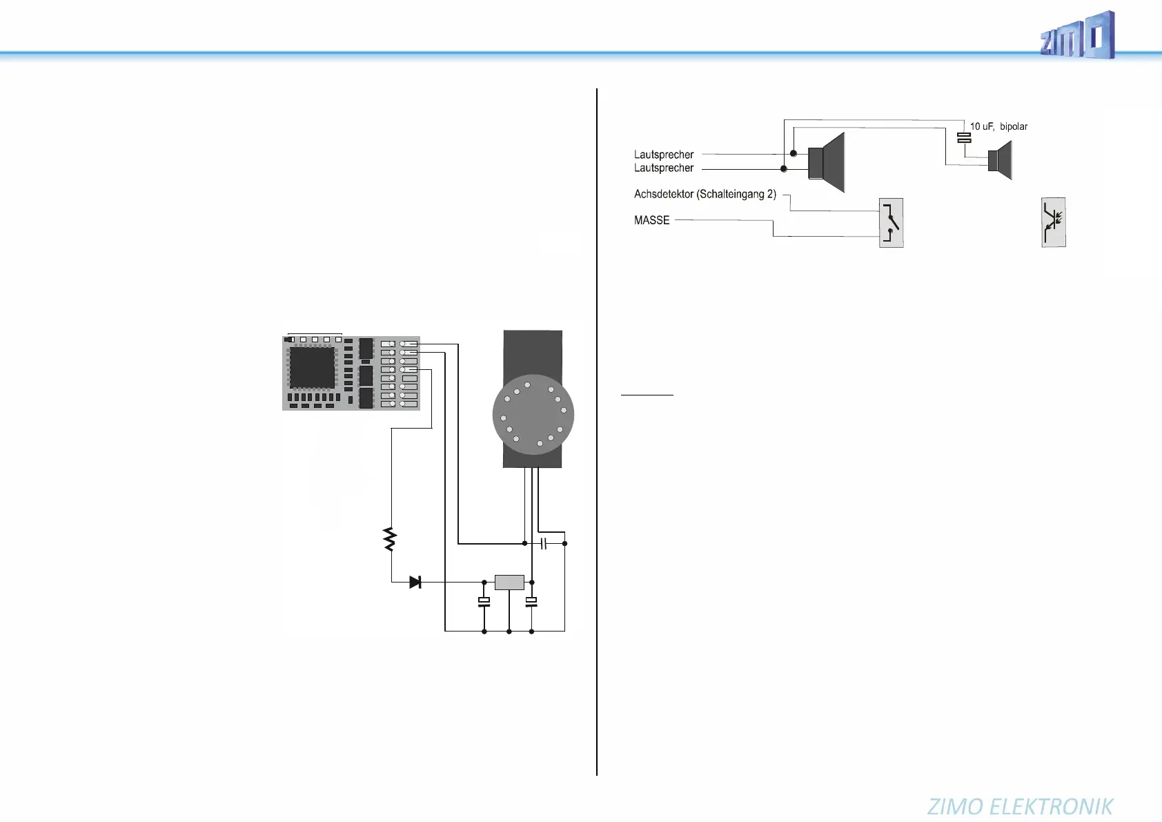
Connecting speaker, cam sensor:
Depending on the type (>= 3 W sound or 1 W sound), a 4 ohm or 8 ohm LOUDSPEAKER can be used,
or several interconnected speakers with a total impedance of 4 ohm or 8 ohm.
Speakers with higher impedance are of course also allowed, but with a loss in volume.
An additional tweeter (also 8 ohm or higher) can be connected, if desired; the connection should be
made via a bipolar capacitor (10 μF bipolar for 2 kHz frequency) to protect the tweeter.
CAM SENSOR: ZIMO Sound Decoders are normally set to the "simulated cam sensor", which is ad-
justed by using CV #267 and #354. If a "real" cam sensor is to be used, CV #268 must be set to 1 or 2,
depending on whether every pulse or every second pulse should trigger a chuff. Mechanical contacts,
Reed switches, optical switches and Hall Effect switches are suitable as cam sensors.
Connecting smoke generators to steam or diesel engines:
“Seuthe” 18 V smoke generators:
In addition to a simple ON/OFF function and a function output of your choice, these decoders are also
capable of adapting the smoke volume to the load (almost no smoke at standstill, little smoke while
cruising, heavy smoke at start-up etc.).
The smoke generator must be connected to one of the function outputs FO1 to FO6 and the selected output
must be programmed with the associated special effect CV (CV #127 for FO1, CV #128 for FO2 etc.) for
the desired effect; in this case for load dependent smoke for steam engines (effect code “72”) or load
dependent smoke for diesels (effect code “80”).
EXAMPLE: - Typical characteristic for a track voltage set around 20 V with above smoke generator:
CV #137 = 70 - 90: little smoke at standstill.
CV #138 = 200: The smoke generator output is increased to about 80 % of its maximum capacity begin-
ning with speed step 1 (lowest speed step), which produces relatively heavy smoke.
CV #139 = 255: The smoke generator is driven to its maximum, which results in thick smoke under heavy
acceleration.
Synchronized steam chuffs or typical diesel smoke with fan-controlled smoke generators:
ZIMO sound decoders, with the help of a smoke generator with built-in fan, can produce steam puffs
synchronized with sound chuffs or load dependent diesel smoke (i.e., diesel engine smoke at start-up,
controlled by the sound project) without additional electronic components.
The heating element of the smoke generator is connected – as in the example above with the “Seuthe”
generator – to FO1 - FO6 and configured with the appropriate CV for the desired effect (i.e., “72” for
steam or “80” for diesel). The fan is connected to the function output FO4 (or FO2 in exceptional cases
such as the MX646); the other wire of the fan motor often requires a low voltage (check with the manu-
facturer) and is therefore connected to an external voltage regulator or – if the fan motor requires 5 V –
to the 5 V supply of the decoder, if such an output is available.
The CVs must be programmed as follows:
CV #137, #138, #139 = 60, 90, 120 respectively: (IMPORTANT) if the heating element cannot operate
at full track voltage, it must be limited by programming suitable values in CV #137, #138 and #139.
CV #133 = 1: (IMPORTANT) this configures output FO4 as a fan output.
CV #353 = ... i.e., 10: shuts the smoke generator off automatically to prevent overheating.
In this example (“10”) after 250 seconds.
CV #351, #352 = …: Only for diesel engines when special effect code “80” is selected in the applicable
CV for FO1 - FO6. This defines the fan speed (voltage) for start-up (default: maximum smoke) and
cruising (default: medium smoke); see CV table.
CV #355 =…: For steam and diesel engines. Defines the fan speed (voltage) at standstill (usually for
very little smoke output).
Outp
GND
V +
Hallsensor,
z.B. TLE4905
8 Ohm - Lautsprecher
8 Ohm -
Lautsprecher
Treibrad
mit Magneten
Mechanischer
Kontaktgeber oder
Reedkontakt (magnet.)
oder Opto-Sensor
optionell:
Hochtöner
 Loading...