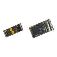
Page 58 Non-Sound Decoder MX618 - MX638 and Sound Decoder MX640 - MX659
MX642, MX644, MX645 …
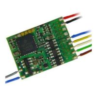
More recent sound decoder versions are to be wired the same
way, except that
- GROUND, switch input and common power are on
solder pads on the top right side or from the blue wire
(common power), and
- only 2 LED outputs (MX642) or none at all, which when
available are accessible at the SUSI solder pads on
the decoders top-side.
Also see the decoder schematics on the front pages of this
manual.
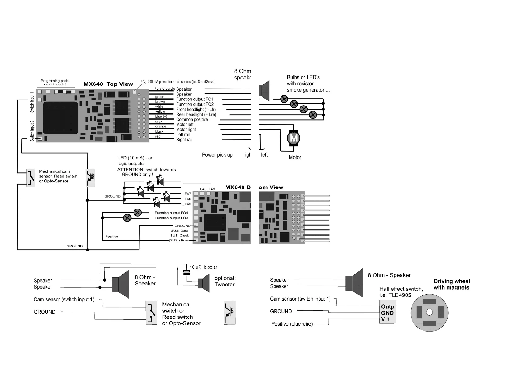
MX640… – Complete Schematic including Sound Connections
Connecting speaker, cam sensor:
In order to operate the MX640 as a sound decoder, the following items
must/may be connected:
- mandatory – SPEAKER – Any 8-ohm speaker or two 4 Ohm speak-
ers connected in series can be used. Speaker with higher impedance
are also allowed but will result in reduced volume.
An additional tweeter (also 8 Ohms or higher) can be connected, if de-
sired; the connection should be made via a bipolar capacitor (10 uF bi-
polar for 2 kHz frequency).
- optional – CAM SENSOR – Normally, ZIMO decoders are pro-
grammed for the “virtual cam sensor”, which can be fine-tuned with CV
#267 and CV #354. If a real cam sensor is to be used, the settings of
CV #268 must be changed to 1 or 2 depending on whether each pulse
or every second pulse should trigger a chuff beat.
Mechanical contacts, Reed switches, optical switches and Hall Effect
switches are suitable as cam sensors.