Non-Sound Decoder MX600 - MX638 and Sound Decoder MX640 - MX659 Page 31
which defines the PWM duty cycle (Pulse Width Modulation; the dimming is also effective when con-
nected to the positive terminal of a low-voltage function output). Of course, this kind of voltage reduc-
tion is interesting because it is easy to change at any time by changing the value in CV #60.
NOTE: Bulbs with voltage ratings as low as 12V can be dimmed with this PWM dimming function with-
out damage even if track voltages are considerably higher; but not bulbs rated below that such as 5V or
1.2V bulbs. These must be connected to one of the decoder’s low voltage supply pins instead of a
“normal” positive pin (see chapter “Installation and Wiring”).
LED’s, on the other hand, always require a series resistor; if however, a resistor is selected that lowers
the voltage to 5 V, the PWM dimming can also be used even at a track voltage of 25V (in this case the
setting would be CV #60 = 50, so a reduction to one fifth).
CV #60 affects all function outputs but specific outputs can be excluded from the dimming function,
using the dim mask CV’s (see table).
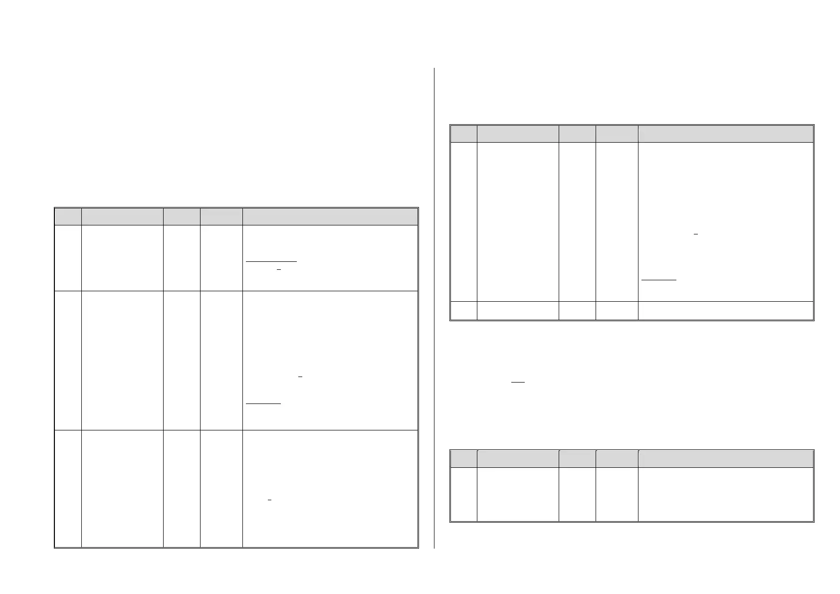
Reduced function output
voltage
(Dimming).
Affects all
function outputs.
Reduction of function output voltage with PWM (pulse-
width modulation). Useful for headlight dimming for
example.
Example values:
CV #60 = 0 or 255: full voltage
CV #60 = 170: 2/3 of full voltage.
CV #60 = 204: 80% of full voltage.
Dim Mask 1
=
Excludes certain
function outputs from
dimming per CV #60.
For higher function
outputs go to
CV #152.
Enter function outputs that are not to be dimmed by
CV #60. These outputs will receive the full voltage
from the pin they are connected to that is, either full
track voltage or low voltage from a low-voltage pin.
Bit 0 - front headlight,
Bit 1 - rear headlight,
Bit 2 - function output FO1, Bit 3 - FO2,
Bit 4 - function output FO3, Bit 5 - FO4
Bit 6 - function output FO5, Bit 7 - FO6
Respective Bit = 0: Output will be dimmed to the value
defined in CV #60.
Respective Bit = 1: Output will not be dimmed.
EXAMPLE:
CV #114 = 60: FO1, FO2, FO3 and FO4 will not be
dimmed; front and rear headlights will be dimmed ac-
cording to CV #60.
Dim Mask 2
(Excludes specific func-
tion outputs from dim-
ming as per CV #60)
Continuation of
CV #114
and
FO3, FO4 as direction
bit mapping
Bits
0 - 5
and
Bit 6,
Bit 7
… Continuation of CV #114.
Bit 0 - function output FO7,
Bit 1 - function output FO8,
Bit 2 - function output FO9,
Bit 3 - function output FO10,
Bit 4 - function output FO11,
Bit 5 - function output FO12.
Bit 6 = 0: “normal“
= 1: “Direction bit” to FO3 and FO4 that is,
FO3 is switched on when driving in reverse,
FO4 when driving forward (normal mapping
for FO3 and FO4 is cancelled).
Bit 7 = 1: “Direction bit” for FO9 in Fwd direction.
Low/high beam mask
One of the function keys F6 (CV #119) or F7 (CV #120) can be defined as a low beam key.
Selected function outputs can be dimmed as required with the function turned ON or OFF (inverted
action with Bit 7).
Low beam mask for F6
-
Output assignment for
(example) low/high
beam
headlights
ATTENTION:
Certain settings in
CV #154 (Special output
configurations for OEM
projects) change the
meaning of CV’s #119
and #120 and therefore
will no longer be a low-
beam mask.
Selected outputs will dim, according to the dim value
in CV #60, when the F6 key is actuated.
Typical application: Low/high beam
Bit 0 - front headlight,
Bit 1 - rear headlight,
Bit 2 - function output FO1,
Bit 3 - function output FO2,
Bit 4 - function output FO3,
Bit 5 - function output FO4.
Respective Bit = 0: Output will not be dimmed,
Respective Bit = 1: Output will be dimmed with F6 to
value defined in CV #60.
Bit 7 = 0: normal action of F6.
= 1: inverted action of F6.
EXAMPLE:
CV #119 = 131: Function key F6 toggles headlights
between low and high beam.
Same as CV #119 but with F7 as low beam key.
A “second dim value” with the help of the uncoupler CV
If more function outputs need to be dimmed than CV #60 allows or if some function outputs require a
different voltage and the uncoupler function is not needed on the same vehicle then
CV #115
can be used for an alternative dimming configuration. The respective function outputs must be de-
fined as “uncoupler output” in the corresponding
CV’s #127…#132, #159 and #160
(see “Special effects for function outputs).
Uncoupler control
or
Second dim value
Only active if “uncoupler” function is selected (value
48) in CV #125 …132, 159 or 160:
Tens digit = 0: when used for dimming applications
Ones digit (0 to 9): PWM – voltage reduction
(0 to 90%)