1 2 3 4
ON
5 6 7 8
1
2
4
8
16
32
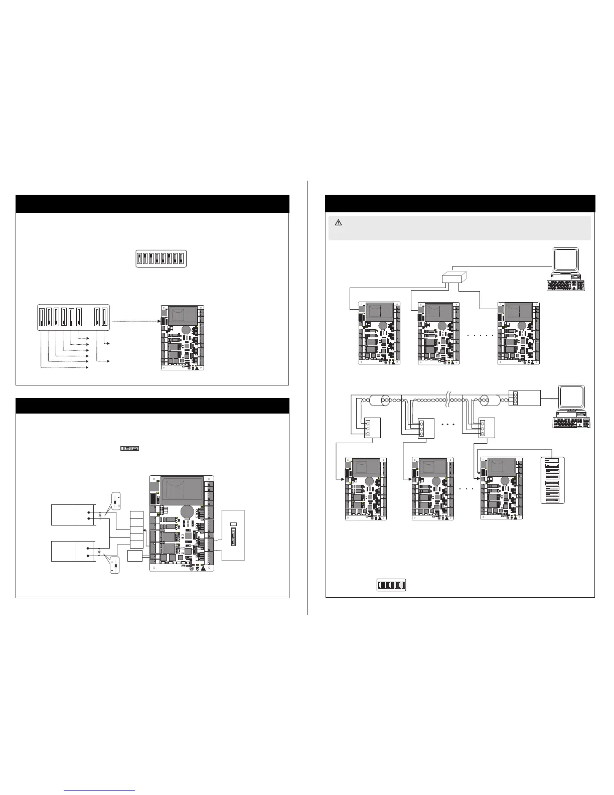
7.Equipment Communication
5、门锁连接
+
+
+
-
-
NC
NO
GND
COM
SEN
+
+
-
-
FR1 07
FR1 07
6.Connection Of Lock
-
PC
PC
LED
1
2
3
4
5
1 2 3 4
5 6 7 8
485+
485-
GND
485+
485+
485+
485-
485-
485-
GND
GND
GND
ON
1
2
3
4
5
5.RS485 Address Setting, Restore Factory Setting, Terminal Resistance Setting
1 2 3 4
ON
5 6 7 8
Location of DIP switch
Set RS485 address through DIP switch:
1) Place 1-6 on DIP switch are for setting the number of control panels when communicating through RS485, it is adopted for binary coding,
and little endian, the address represented by place 1-6 are shown as figurue(5-1).
2) Before setting the address, please keep the system power off, Jump place 1-6 to desired status. The address number cannot be the same as
another one in the network. For example: to set the device number as 39 (39=1+2+4+32), the corresponding RS485 code is 111001,
then Jump place 1,2,3 and 6 at “ON” status.
3) Place 7 is for restoring factory default settings. Jump it for three times within 10 seconds and restart the system. All information in
control panel will be cleared and the system restores factory default settings.RAM
4) Place 8 is for setting terminal resistance when communicating through RS485. Jump it at “ON” status, then it is equivalent to having
a terminal resistance of 120 ohm between 485+ and 485-.
Figure(5- 1 )
Restore factory setting
RS485 terminal resistance
3) When the Electrical Lock is connected to the Access Control System, you need to parallel one FR107
diode (equipped in the package) to
prevent the self-inductance EMF affecting the system, do not reverse the polarities.
1) Control panel provides lock control output interfaces. For NO lock ,it is open when power is on, and closed when power is off, so COM and
NO interfaces should be used; For NC lock, it is open when power is off, and closed when power is on, so COM and NC interfaces should be
used.
2) Contr ol pa nel suppo rts “ dry mode” a nd “w et mode” by s ett ing the jum per, it i s “wet mode ” whe n connect ing “ V+ V-” Input int erf aces to
supply p owe r for locks , please short en 2-3 and 4-5 . Equ ipment facto ry default set tin g is dry mode . For setting “d ry mode” and
please r efe r to <<C3-1 00/ 200/400 a cce ss contro l pan el instal lat ion instr uct ions>>.“wet mod e”,
NO Lock
LOCK
LOCK
“Wet mode” wiring diagram of lock connecting with external power supply.
Enlarged d iagram
of lock p orts
NC Lock
Lock powe r
input
Diode
Diode
Jumper
terminal
1.TCP/IP Communication
2.RS485 Communication
The background PC software is able to communicate with the system according to two protocols(RS485 and TCP/IP) for data exchange and
remote management. The communication cable should be as far away from high-voltage lines as possible. Do not keep the communication cable
in parallel with power cords or bind them together.
Switch
n# control panel
serial line
1# control panel
2# control panel
485
Converter
DIP switch
8# control panel
2# control panel
1# control panel
1) Internationally accepted RVSP(shielded twisted-pair) wires should be used for communication to effectively avoid interference. RS485
of bus cascade connection. communication wires should be connected by means
3) One RS485 BUS may hold 63 control panel , but it is not recommended to connect with more than 32 units .units access control panels.
1 2 3 4 5 6 7 8
ON
Notes:
4)To enhance the stability of communication it is necessary to keep place 8 of DIP when the bus is longer than 300m, switches of
2)Considering stability of communication, it is recommended the length of RS485 bus is less than 600m
is placed at "ON " s tatus.
the first and the last control panel at “ON” status. As shown i n the figure a bove, plac e 8 of the DIP sw itches of un its 1# and 8#
GND
IN
BUTTON2
GND
GND
+12V
+12V
WD1
WD1
WD0
WD0
READER3
GLED
GLED
BEEP
BEEP
GND
+12V
WD1
WD0
READER2
GLED
BEEP
AUX1
AUX2
EXT
BUTTON1
READER1
+12V
GND
WD1
WD0
GLED
BEEP
+12V
GND
485-
485+
GND
GND
IN
IN
IN
GND
TX
RX
ACT
LINK
POWER
CARD
RUN
LAN
1
1
TX
RX
V+
POWER
PC
NC
NC
COM
COM
NO
NO
COM
COM
NO
NO
NC
NC
LOCK1 LOCK2
GND
GND
SEN
SEN
V-
GND
485-
485+
AUXOUT1 AUXOUT2
LOCK
GND
+12V
1 2 3 4
ON
5 6 7 8
SD card
Advanced Access Control
READER4
GND
IN
BUTTON2
GND
GND
+12V
+12V
WD1
WD1
WD0
WD0
READER3
GLED
GLED
BEEP
BEEP
GND
+12V
WD1
WD0
READER2
GLED
BEEP
AUX1
AUX2
EXT
BUTTON1
READER1
+12V
GND
WD1
WD0
GLED
BEEP
+12V
GND
485-
485+
GND
GND
IN
IN
IN
GND
TX
RX
ACT
LINK
POWER
CARD
RUN
LAN
1
1
TX
RX
V+
POWER
PC
NC
NC
COM
COM
NO
NO
COM
COM
NO
NO
NC
NC
LOCK1 LOCK2
GND
GND
SEN
SEN
V-
GND
485-
485+
AUXOUT1 AUXOUT2
LOCK
GND
+12V
1 2 3 4
ON
5 6 7 8
SD card
Advanced Access Control
READER4

 Loading...