6
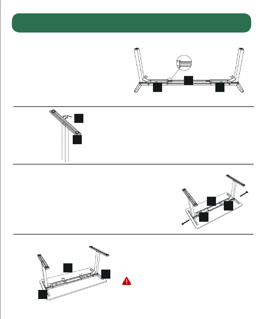
Slide the two (2) Centre Rails (part
5) into the two Frame Ends (parts
3 & 4) ensuring: a} the slots in the
Centre Rail (part 5) face inward b}
the slots in the Centre Rail (part 5)
are closer to the top edge when
the assembly is upside down (see
inset).
For each leg assembly, attach a Foot (part 2) with four (4)
M6x14 Machine Screws (part l 1) and tighten in a cross-
pattern.
Check both sides of the desktop before placing the
desk base on the underside of the desktop.
Adjust the width of the desk base to t the desktop
by sliding the two halves outward. We recommend
leaving at least 1/2” of the desktop width (on each
end) protruding beyond the frame width and centring
the side brackets (part 6) before and after.
Lock the position of the Centre Rail (part 5)
using eight (8) M6x10 Machine Scews (part 12).
Ensure the M6x10 Machine Screws (part 12)
contacts the Centre Rail (part 5) by sliding the
Centre Rail (part 5) as needed.
Assembly
4
5
6
7
5
3 4
11
2
3
4
5
10
10
12
 Loading...