ZXA10 S300 (V1.1) Integrated Access Service Dispatching Unit Technical Manual
14 Confidential and Proprietary Information of ZTE CORPORATION
Hardware Structure
This section introduces the overall system architecture and
board types.
Overall System Architecture
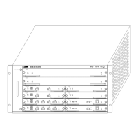
The ZXA10 S300 system has a standard plug-in box that is 19
inches wide and 5 U tall, as shown in
Figure 8.
FIGURE 8 − STRUCTURE OF THE ZXA10 S300 PLUG-IN BOX
OL1A
OL1A
OL4A
FAN UNIT
TAA
TAA
OL16A
ES
ES
E1C
E1C
ZXA10-IS300
Dimensions of the 5 U standard sub-rack: 221.6 mm × 482.6
mm × 477 mm (Height × Width × Depth).
The sub-rack has six layers with an opposite insertion structure.
Ten boards can be inserted into the front panel and six boards
can be inserted into the back panel. There are two indicators and
one ESD bonding point in the right bottom. The CST indicator is
the same as the RUN indicator of the NOWC board. The FTS
indicators indicate the temperature status of the fan. For details
of the FTS indicator, see
Table 4.
TABLE 4 − FTS INDICATION
Indicator State Indication
Off The NE is not powered on (or the NOWC board is not
in position).
Green Both the temperature and fans are normal.
FTS
Red The temperature is not at a normal level or the fans
become faulty.
 Loading...