ZXR10ZSRV2HardwareDescription
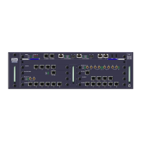
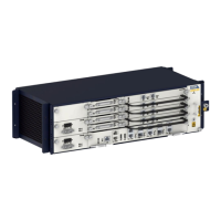
Figure3-2FrontViewoftheZXR102800-4Chassis
1.Powersupplymodule
2.SPIUlineinterfaceboard
slots
3.PIU/DPIUlineinterface
boardslots
4.Fanmodule
5.MPFUslots
ForadescriptionofthemaincomponentsoftheZXR102800-4chassis,refertoT able3-1.
Table3-1DescriptionoftheMainComponentsoftheZXR102800-4Chassis
ComponentNameDescription
BoardareaTheZXR102800-4providesoneslotforthemaincontrol
forwardingboardandatmostfourslotsforlineinterfaces.
PowersupplymoduleTheZXR102800-4providestwoslotsforpowermodules.Youcan
congureoneortwopowermodules.
FanmoduleTheZXR102800-4providesoneverticallyinstalledfanmodule.
3.1.2SlotLayout
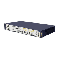
ForafrontviewoftheZXR102800-4chassis,seeFigure3-3.
Figure3-3FrontViewoftheZXR102800-4Chassis
TheZXR102800-4chassisprovidesveserviceslotsandboardsarehorizontallyinstalled
inthechassis.
lTheMPFUisinstalledinslot4.
lPIUs/DPIUsandSPIUsareinstalledinslots0to3.
TheSPIUslotsareapplicabletoSPIUboards.ThePIUslotsareapplicabletoPIU
boards.TheDPIUboardusestwoslots,includingonePIUslotanditsneighboring
PIU/DPIUslot.
3-2
SJ-20150204153047-004|2015-03-30(R1.0)ZTEProprietaryandCondential
 Loading...