For technical questions, please call 1-888-866-57976
About the Scan Tool
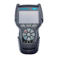
DISPLAY FUNCTIONS
3
5. M (Menu) button – When pressed, displays the Main Menu.
6. LD button – When pressed while linked to a vehicle, places the
Scan Tool in Live Data mode.
7. UP button – When in MENU mode, scrolls UP through the
menu options. When LINKED to a vehicle, scrolls UP through the
current display screen to display any additional data.
8. ENTER button - When in Menu mode, confirms the selected
option or value.
9. DOWN button - When in MENU mode, scrolls down through the
menu options.
When LINKED to a vehicle, scrolls down through the
current display screen to display any additional data.
10. GREEN LED - Indicates that all engine systems are running
normally (all Monitors on the vehicle are active and performing
their
diag
nostic testing, and no DTCs
are present).
11. YELLOW LED - Indicates there is a possible problem. A “Pending”
DTC is present and/or some of the vehicle's emission monitors have
not run their diagnostic testin
g.
12. RED LED - Indicates there is a problem in one or more of the
vehicle's systems. The red LED is also used to show that DTC(s)
are present. DTCs are shown on the Scan Tool’s LCD display. In
this case, the Malfunction Indicator (“Check Engine”) lamp
on the
vehicle's instrument panel will light steady on.
13. Display - Displays test results, Scan Tool functions and Monitor status
information. See DISPLAY FUNCTIONS, below, for details.
14. CABLE - Connects the Scan Tool to the vehicle's Data Link Connecto
r
(DLC).
DISPLAY FUNCTIONS
Figure 2. Display Functions
See Figure 2 for the locations of items 1 through 15, below.
1. I/M MONITOR STATUS field - Identifies the I/M Monitor status area.
4
3
2
5
7
6
114
10
11
12
8
9
13
15
CODE RETRIEVAL PROCEDURE
Using the Scan Tool
CODE RETRIEVAL PROCEDURE
6
Retrieving and using Diagnostic Trouble Codes (DTCs) fo
troubleshooting vehicle operation is only one part of an
overall diagnostic strategy.
CODE RETRIEVAL PROCEDURE
Never replace a part based only on the DTC definition.
Each DTC has a set of testing procedures, instructions and
flow charts that must be followed to confirm the location of
the problem. Always refer to the vehicle's service manual
for detailed testing instructions.
Check your vehicle thoroughly before performing
any test.
ALWAYS observe safety precautions whenever working on a
vehicle.
1. Turn the ignition off.
2. Locate the vehicle's 16-pin Data Link
Connector (DLC).
Some DLCs have a plastic cover
that must be removed before
connecting the Scan Tool cable
connector.
If the Scan Tool is ON, turn it OFF
BEFORE connecting the Scan
Tool to the DLC.
3. Connect the Scan Tool to the vehicle’s
DLC. The cable connector is keyed and
will only fit one way.
If you have problems connecting the cable connector to the DLC,
rotate the connector 180°.
If you still have problems, check the DLC on the vehicle and on
the Scan Tool.
4. Turn the ignition on. DO NOT start the engine.
5. When the Scan Tool is properly connected to the vehicle’s DLC, the
unit automatically turns ON.
If the unit does not power on automatically, it may indicate there
is no power present at the vehicle’s DLC connector. Check the
fuse panel and replace any burned-out fuses.
If replacing the fuse(s) does not correct the problem, consult your
vehicle’s repair manual to identify the proper computer (PCM)
fuse/circuit, and perform any necessary repairs before proceeding.
 Loading...