Chapter 2 Hardware Description and Connection
GS1100 Series User’s Guide
14
2.3 Hardware Installation
See the following table for a comparison of the hardware installation methods of each GS1100
model:
Table 5 GS1100 Series Installation Comparison Table
Note: Ask an authorized technician to attach the Switch to the rack/wall.
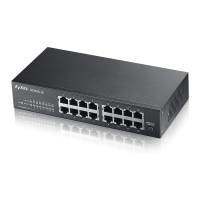
For GS1100-8HP, GS1100-16 and GS110-24E, you can place the Switch directly on top of your desk
or have it wall-mounted. For GS1100-16, GS1100-24 and GS110-24E, the size is suitable for rack-
mounting and you can refer to Section 2.3.2 on page 15 for instruction. Take note of the following:
• The Switch should have a minimum 25 mm space around it for ventilation.
• The Switch should be placed in a desk that has a level surface and that is able to support the
weight of the Switch.
To start using it, simply connect the power cables and turn on the Switch.
2.3.1 Wall Mounting
Do the following to attach your Switch to a wall.
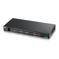
10/100 Amber On The port is connected to an Ethernet network at 10M or 100M speed.
Blinking The port is receiving or transmitting data at 10M or 100M speed.
Off The port is not connected to an Ethernet network.
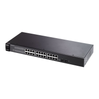
Table 4 The Front Panel LED Descriptions: GS1100-16/24/24E
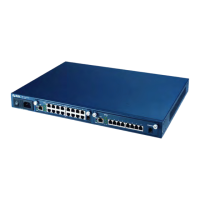
LED COLOR STATUS DESCRIPTION
PWR Green On The Switch is on and receiving power.
Off The Switch is not receiving power.
LINK/
ACT
Green On The port is connected to an Ethernet network.
Blinking The port is receiving or transmitting data.
Off The port is not connected to an Ethernet network.
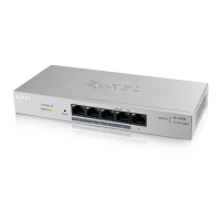
Table 3 The Front Panel LED Descriptions: GS1100-8HP
LED COLOR STATUS DESCRIPTION
MODEL FEATURE GS1100-8HP GS1100-16 GS1100-24 GS1100-24E
Desktop Device
Wall-mountable
Rack-mountable
 Loading...