GS1500-24P User’s Guide
31
CHAPTER 3
Hardware Panels
3.1 Overview
This chapter describes the front panel and rear panel of the Switch and shows you
how to make the hardware connections.
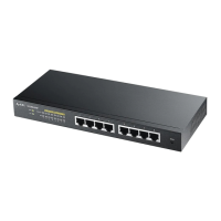
3.2 Front Panel
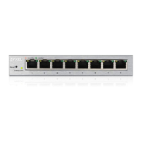
The following figure shows the front panel of the Switch.
Figure 7 Front Panel
The following table describes the port labels on the front panel.
Ethernet Ports
Dual Personality Interfaces
LEDs
Table 1 Front Panel Connections
LABEL DESCRIPTION
24 10/100/
1000 RJ-45
Ethernet
Ports
Connect these ports to a computer, a hub, an Ethernet switch or router.
 Loading...