Chapter 3 Hardware Overview
GS1900 Series User’s Guide
32
Fig ure 26 Removing the Fiber Cables
Fig ure 27 Opening the Transceiver’s Latch Example
Fig ure 28 Transceiver Removal Example
3.1.3 Po E Mo de (G S1900- 48HP a nd G S1900- 48HPv2 o nly)
Push or release this button (see
Figure 21 on page 29) to change how the Link/ AC T LED works.
• Each Ethernet port’s LED is changed to act as a Po E Mo de LED by pushing the Po E MO DE button on
the front panel.
• Each Ethernet port’s LED is changed back to act as a Link/ AC T LED by releasing the Po E MO DE button
on the front panel.
View the LEDs to ensure proper functioning of the Switch and as an aid in troubleshooting (see
Section
3.3 on page 37).
3.2 Re a r Pa ne l
The following figures show the rear panels of the Switch.
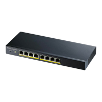
Fig ure 29 Rear Panel: GS1900-8
 Loading...