Chapter 3 Hardware Panels
XGS1210-12 User’s Guide
15
CHAPTER 3
Hardware Panels
This chapter describes the front panel and rear panel of the Switch and shows you how to make the
hardware connections.
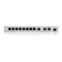
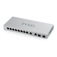
3.1 Front Panel
The following figure shows the front panel of the Switch.
Figure 8 Front Panel
3.2 Rear Panel
The following figure shows the rear panel of the Switch.
Figure 9 Rear Panel
3.2.1 Power Connector
Note: Make sure you are using the correct power source as shown on the panel.
To connect power to the Switch, insert the female end of the power cord to the AC power receptacle
on the rear panel. Connect the other end of the supplied power cord to a power outlet. Make sure that
no objects obstruct the airflow.
 Loading...