EasyManua.ls Logo

2VV ALFA EC Series User Manual

2VV ALFA EC Series
49 pages
To Next Page IconTo Next Page
Page #1 background imageLoading...
Page #1 background image
ALFA EC
FULL MANUAL
INSTALLATION AND OPERATION
EN
ver.1 28.05.20
Question and Answer IconNeed help?

Do you have a question about the 2VV ALFA EC Series and is the answer not in the manual?

2VV ALFA EC Series Specifications

General IconGeneral
Brand2VV
ModelALFA EC Series
CategoryFan
LanguageEnglish

Summary

1 - BEFORE STARTING

1.1 – DETAILS ABOUT THE MANUAL

Explains symbols used for orientation in the manual.

1.2 - INFORMATION ABOUT THE PRODUCT AND INSTALLATION

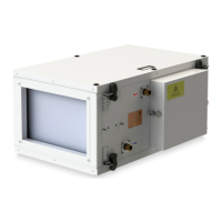
Describes the unit's function, design, and operating conditions.

1.3 DECLARATION OF CONFORMITY

States compliance with applicable EU provisions and standards.

2 – UNPACKING

2.1 – CONTROLLING THE DELIVERY

Instructions for checking product condition and contents upon delivery.

2.2 - UNPACKING THE UNIT

Guidance on safely unpacking the ventilation unit and its components.

3 - MAIN PART

Main Unit Components

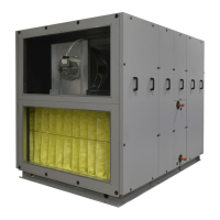
Identifies key components of the Alfa4 EC unit.

4 - DIMENSIONS

AHAL4-05-EL Electric Heat Exchanger Dimensions

Dimensional specifications for the AHAL4-05-EL model.

AHAL4-05-S Without Reheating Dimensions

Dimensional specifications for the AHAL4-05-S model.

AHAL4-05-VV Water Heat Exchanger Dimensions

Dimensional specifications for the AHAL4-05-VV model.

C/O External Module AHAL4-05 Dimensions

Dimensional specifications for the C/O External Module AHAL4-05.

DX External Module AHAL4-05 Dimensions

Dimensional specifications for the DX External Module AHAL4-05.

AHAL4-10-EL Electric Heat Exchanger Dimensions

Dimensional specifications for the AHAL4-10-EL model.

AHAL4-10-S Cold Dimensions

Dimensional specifications for the AHAL4-10-S model.

AHAL4-10-VV Water Heat Exchanger Dimensions

Dimensional specifications for the AHAL4-10-VV model.

C/O External Module AHAL4-10 Dimensions

Dimensional specifications for the C/O External Module AHAL4-10.

DX External Module AHAL4-10 Dimensions

Dimensional specifications for the DX External Module AHAL4-10.

AHAL4-20-EL Electric Heat Exchanger Dimensions

Dimensional specifications for the AHAL4-20-EL model.

AHAL4-20-S Cold Dimensions

Dimensional specifications for the AHAL4-20-S model.

AHAL4-20-VV Water Heat Exchanger Dimensions

Dimensional specifications for the AHAL4-20-VV model.

C/O External Module AHAL4-20 Dimensions

Dimensional specifications for the C/O External Module AHAL4-20.

DX External Module AHAL4-20 Dimensions

Dimensional specifications for the DX External Module AHAL4-20.

AHAL4-30-EL Electric Heat Exchanger Dimensions

Dimensional specifications for the AHAL4-30-EL model.

AHAL4-30-S Without Reheating Dimensions

Dimensional specifications for the AHAL4-30-S model.

AHAL4-30-VV Water Heat Exchanger Dimensions

Dimensional specifications for the AHAL4-30-VV model.

C/O External Module AHAL4-30 Dimensions

Dimensional specifications for the C/O External Module AHAL4-30.

DX External Module AHAL4-30 Dimensions

Dimensional specifications for the DX External Module AHAL4-30.

AHAL4-50-S Without Reheating Dimensions

Dimensional specifications for the AHAL4-50-S model.

AHAL4-50-VV Dimensions

Dimensional specifications for the AHAL4-50-VV model.

C/O External Module AHAL4-50 Dimensions

Dimensional specifications for the C/O External Module AHAL4-50.

DX External Module AHAL4-50 Dimensions

Dimensional specifications for the DX External Module AHAL4-50.

AHAL4-80-S Dimensions

Dimensional specifications for the AHAL4-80-S model.

AHAL4-80-VV Dimensions

Dimensional specifications for the AHAL4-80-VV model.

C/O External Module AHAL4-80 Dimensions

Dimensional specifications for the C/O External Module AHAL4-80.

5 - TECHNICAL PARAMETERS

Control panel

Control Panel Technical Information

Information related to the control panel's technical aspects.

6.4.4 - CONNECTING THE INTAKE AND EXHAUST UNITS

6.4.6 – INSTALLATION – EXTERNAL C/O, DX MODULE (accessories)

6.5 – CONNECTING THE WATER EXCHANGER (HEATER, COOLER)

6.6 - CONDENSATE DRAIN CONNECTION

7 - COMMISSIONING

Commissioning Setup Examples

Illustrates normal siphon and ball trap for commissioning.

7.1 STARTUP

8 - MAINTENANCE

8.1 FILTER CHANGE

Procedure for changing the unit's filter.

8.2 - REGULAR CLEANING

9 – TROUBLESHOOTING

Troubleshooting Technical Information

Explains how errors are signaled via the control's display.

10 – DECOMMISSIONING THE PRODUCT – LIQUIDATOIN

Product Decommissioning Steps

Details procedures for disassembling engine, circuit, and plastic parts.

11 – CONCLUSION

CONTACT

Related product manuals