118 CHAPTER 6: IP ROUTING PROTOCOL OPERATION
Example: Typical Static
Route Configuration
Networking Requirements
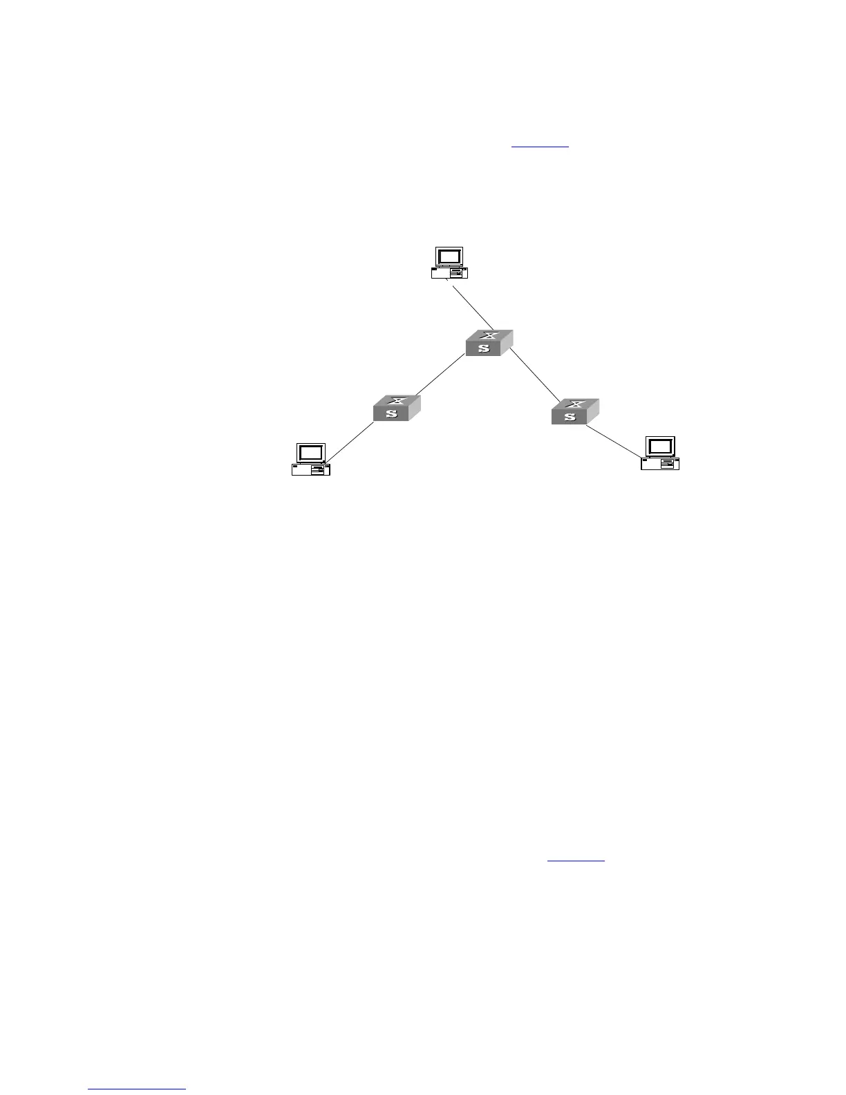
The masks of all the IP addresses shown in Figure 30 are 255.255.255.0. All the
hosts or switches must be interconnected in pairs by configuring static routes.
Networking Diagram
Figure 30 Networking diagram of the static route configuration example
Configuration procedure
1 Configure the static route for Ethernet Switch A
[Switch A]ip route-static 1.1.3.0 255.255.255.0 1.1.2.2
[Switch A]ip route-static 1.1.4.0 255.255.255.0 1.1.2.2
[Switch A]ip route-static 1.1.5.0 255.255.255.0 1.1.2.2
2 Configure the static route for Ethernet Switch B
[Switch B]ip route-static 1.1.2.0 255.255.255.0 1.1.3.1
[Switch B]ip route-static 1.1.5.0 255.255.255.0 1.1.3.1
[Switch B]ip route-static 1.1.1.0 255.255.255.0 1.1.3.1
3 Configure the static route for Ethernet Switch C
[Switch C]ip route-static 1.1.1.0 255.255.255.0 1.1.2.1
[Switch C]ip route-static 1.1.4.0 255.255.255.0 1.1.3.2
4 Configure the default gateway of the Host A to be 1.1.5.2
5 Configure the default gateway of the Host B to be 1.1.4.1
6 Configure the default gateway of the Host C to be 1.1.1.2
Using this procedure, all the hosts or switches in Figure 30 can be interconnected
in pairs.
Troubleshooting Static
Routes
The Switch 5500G-EI is not configured with the dynamic routing protocol enabled.
Both the physical status and the link layer protocol status of the interface are
enabled, but the IP packets cannot be forwarded normally.
Troubleshooting:
■ Use the display ip routing-table protocol static command to view
whether the corresponding static route is correctly configured.
A
B
C
Host 1.1.5.1
1.1.5.2/24
1.1.2.2/24
1.1.2.1/24
1.1.1.2/24
Host 1.1.1.1
Host 1.1.4.2
1.1.3.1/24
1.1.3.2/24
1.1.4.1/24
Switch A
Switch B
Switch C
 Loading...