OSPF Configuration 151
Networking Diagram
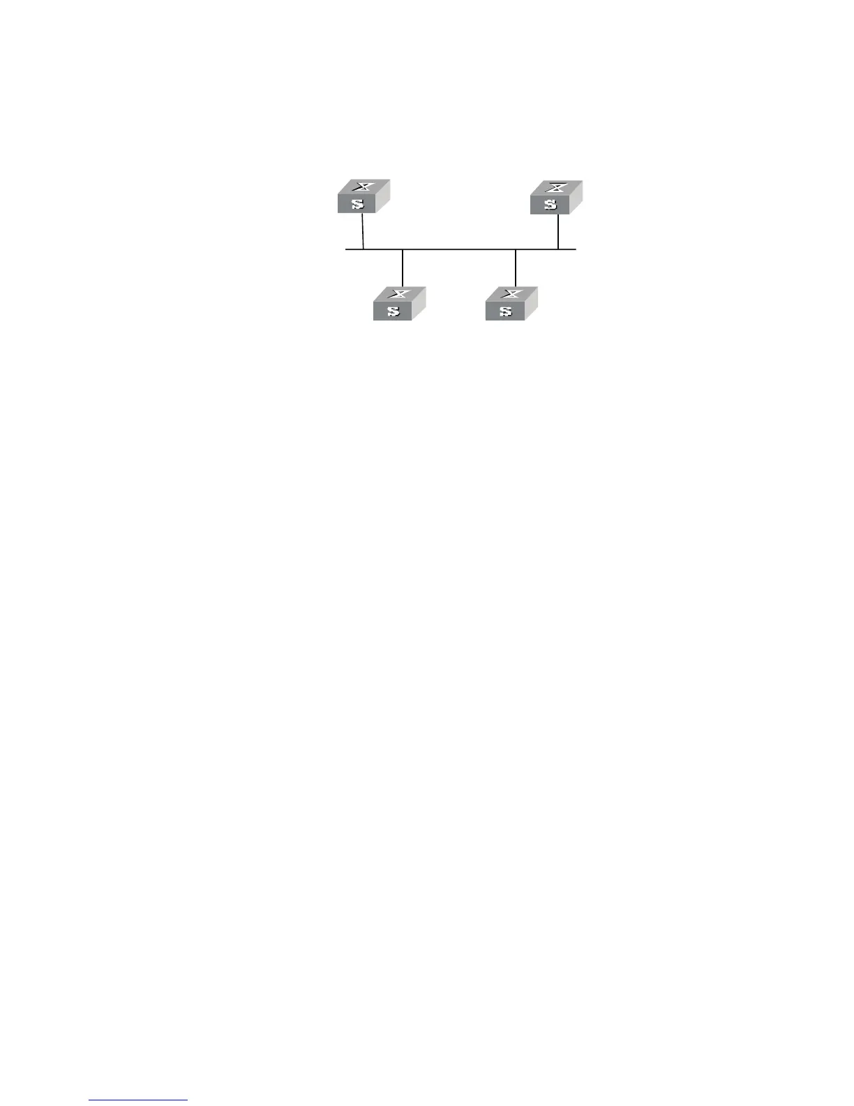
Figure 33 Networking for configuring DR election based on OSPF priority
The commands listed in the following examples enable Switch A and Switch C to
be DR and BDR, respectively. The priority of Switch A is 100, which is the highest
on the network, so it is elected as the DR. Switch C has the second highest priority,
so it is elected as the BDR. The priority of Switch B is 0, which means that it cannot
be elected as the DR, and Switch D does not have a priority, and therefore takes
priority 1 by default.
Configuration Procedure
1 Configure Switch A:
[Switch A]interface Vlan-interface 1
[Switch A-Vlan-interface1]ip address 196.1.1.1 255.255.255.0
[Switch A-Vlan-interface1]ospf dr-priority 100
[Switch A]router id 1.1.1.1
[Switch A]ospf
[Switch A-ospf-1]area 0
[Switch A-ospf-1-area-0.0.0.0]network 196.1.1.0 0.0.0.255
2 Configure Switch B:
[Switch B]interface Vlan-interface 1
[Switch B-Vlan-interface1]ip address 196.1.1.2 255.255.255.0
[Switch B-Vlan-interface1]ospf dr-priority 0
[Switch B]router id 2.2.2.2
[Switch B]ospf
[Switch B-ospf-1]area 0
[Switch B-ospf-1-area-0.0.0.0]network 196.1.1.0 0.0.0.255
3 Configure Switch C:
[Switch C]interface Vlan-interface 1
[Switch C-Vlan-interface1]ip address 196.1.1.3 255.255.255.0
[Switch C-Vlan-interface1]ospf dr-priority 2
[Switch C]router id 3.3.3.3
[Switch C]ospf
[Switch C-ospf-1]area 0
[Switch C-ospf-1-area-0.0.0.0]network 196.1.1.0 0.0.0.255
4 Configure Switch D:
[Switch D]interface Vlan-interface 1
[Switch D-Vlan-interface1]ip address 196.1.1.4 255.255.255.0
[Switch D]router id 4.4.4.4
[Switch D]ospf
BDR
196.1.1.4/2 4
196.1.1.3 /24
19 6.1.1.2/24
DR
Switch A
Switch D
Switch B Switch C
1.1.1.1
4.4 .4.4
3.3.3 .3
2.2.2.2
19 6.1.1.1/24