IP Routing Policy 161
Displaying and
Debugging the Routing
Policy
Enter the display command in any view to display the operation of the routing
policy configuration, and to verify the effect of the configuration.
Typical IP Routing Policy
Configuration Example
Configuring the Filtering of the Received Routing Information
Networking Requirements
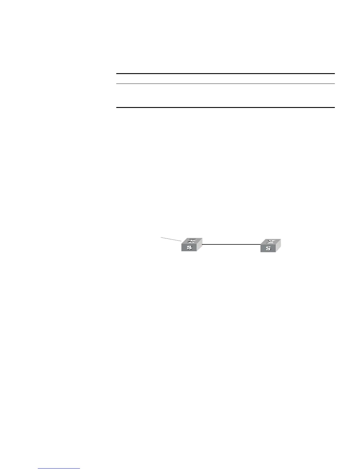
■ Switch A communicates with Switch B, running OSPF protocol.
■ Import three static routes by enabling the OSPF protocol on Switch A.
■ The route filtering rules can be configured on Switch B to make the received
three static routes partially visible and partially shielded. This means that routes
in the network segments 20.0.0.0 and 40.0.0.0 are visible while those in the
network segment 30.0.0.0 are shielded.
Networking diagram
Figure 36 Filtering the received routing information
Configuration procedure
1 Configure Switch A:
a Configure the IP address of VLAN interface.
[Switch A]interface vlan-interface 100
[Switch A-Vlan-interface100]ip address 10.0.0.1 255.0.0.0
[Switch A]interface vlan-interface 200
[Switch A-Vlan-interface200]ip address 12.0.0.1 255.0.0.0
b Configure three static routes.
[Switch A]ip route-static 20.0.0.1 255.0.0.0 12.0.0.2
[Switch A]ip route-static 30.0.0.1 255.0.0.0 12.0.0.2
[Switch A]ip route-static 40.0.0.1 255.0.0.0 12.0.0.2
c Enable OSPF protocol and specifies the number of the area to which the
interface belongs.
[Switch A]router id 1.1.1.1
[Switch A]ospf
[Switch A-ospf-1]area 0
[Switch A-ospf-1-area-0.0.0.0]network 10.0.0.0 0.255.255.255
d Import the static routes
[Switch A-ospf-1]import-route static
Tab le 170 Displaying and Debugging the Routing Policy
Operation Command
Display the routing policy display route-policy [
route_policy_name
]
Display the address prefix list
information
display ip ip-prefix [
ip_prefix_name
]
area 0
sta tic 20.0.0 .0/8
30.0.0.0 /8
40.0.0.0 /8
R o u ter ID:1.1.1.1
10.0 .0.2/8
Switch A
Swit ch B
Vlan-interface200
12.0 .0.1/8
Router ID:2.2.2.2
Vlan-in terface10 0
10.0.0 .1/8 Vlan- in terface1 00