DHCP Configuration 99
DHCP Relay
Configuration Example
One
Networking Requirements
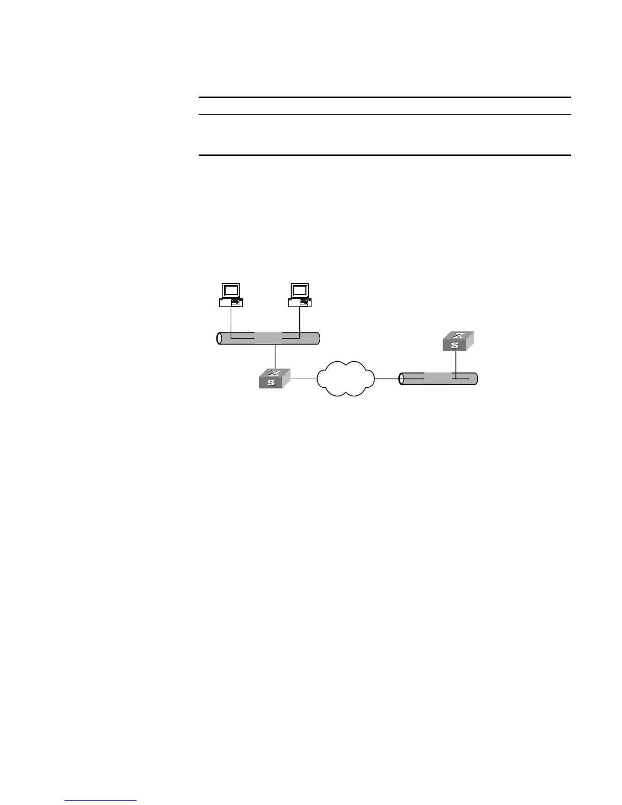
There are two VLANs (1 and 10) and they both need to use the same DHCP server.
Networking Diagram
Figure 24 Configuring DHCP Relay
Configuration Procedure
1 Create a DHCP server group that will use two DHCP servers (a master and an
optional backup) and assign it the IP addresses of the two DHCP servers (the first
IP address is the master).
[SW5500]dhcp-server 0 ip 192.168.1.1 192.168.2.1
2 Configure the Switch so all clients use DHCP server group '0'.
[SW5500]interface vlan-interface 1
[SW5500-Vlan-interface1]dhcp-server 0
[SW5500-Vlan-interface1]quit
[SW5500]interface vlan-interface 10
[SW5500-Vlan-interface10]dhcp-server 0
[SW5500-Vlan-interface10]quit
DHCP Relay
Configuration Example
Two
Networking Requirements
The segment address for the DHCP Client is 10.110.0.0, which is connected to a
port in VLAN2 on the Switch. The IP address of the DHCP Server is 202.38.1.2. The
DHCP packets should be forwarded via the Switch with DHCP Relay enabled. A
DHCP Client can get its IP address and other configuration information from the
DHCP Server.
Enable/disable DHCP Client hot backup
debugging
[ undo ] debugging dhcp xrn xha
Enable/disable DHCP relay debugging [ undo ] debugging dhcp-relay
Table 94 Displaying and Debugging DHCP Configuration
Operation Command
Ethernet
Ethernet
Internet
DHCP client
DHCP client
Switch ( DHCP Relay )
10.110.0.0
DHCP Server
202.38.1.2
10.110.1.1
202.38.0.0
202.38.1.1
 Loading...