Access Management Configuration 103
Perform the following configuration in System View.
By default, the access management trap is disabled.
Displaying and
Debugging Access
Management
After the above configuration, enter the display command in any view to display
the current configurations of access management and port isolation information,
and to verify the effect of the configuration.
Access Management
Configuration Example
Networking Requirements
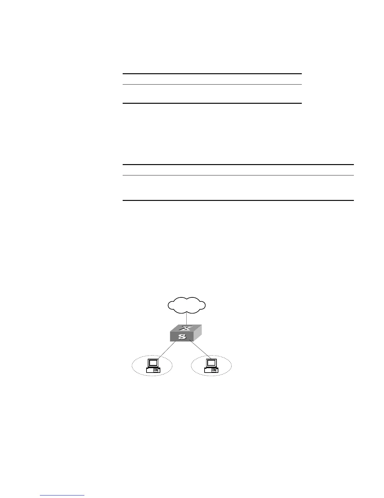
Organization 1 is connected to port 1 of the Switch, and organization 2 to port 2.
Ports 1 and 2 belong to the same VLAN. The IP addresses range 202.10.20.1 to
202.10.20.20 can be accessed from port 1 and the range 202.10.20.21 to
202.10.20.50 from the port 2. Organization 1 and organization 2 cannot
communicate with each other.
Networking Diagram
Figure 26 Networking Diagram for Port Isolation Configuration
Configuration Procedure
1 Enable access management globally.
[SW5500]am enable
2 Configure the IP address pool for access management on port 1.
[SW5500]interface gigabitethernet1/0/1
[SW5500-GigabitEthernet1/0/1]am ip-pool 202.10.20.1 20
3 Add port 1 into isolation group.
[SW5500-GigabitEthernet1/0/1]port isolate
Tab le 98 Enabling/Disabling Access Management Trap
Operation Command
Enable access management trap am trap enable
Disable access management trap undo am trap enable
Tab le 99 Displaying Current Configuration of Access Management
Operation Command
Display the status of access management
function and configuration of IP address pool
display am [
interface-list
]
Display port isolation information display isolate port
External
Network
E 0/1
E 0/2
 Loading...