IM 725 (1-02) 3
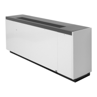
Figure 1 – Typical Classroom Unit Ventilator Installation And Louver Details (see installation section for typical warnings and cautions)
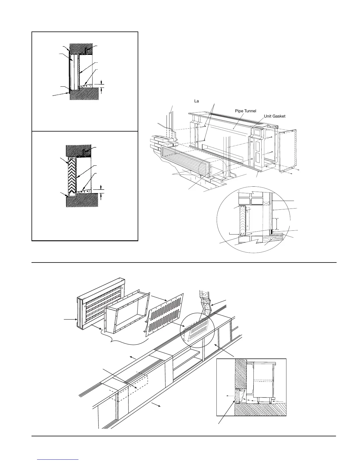
Figure 2 – Typical VentiMatic
™
Shutter Assembly Installation (see installation section for typical warnings and cautions)
Unit Gasket
Pipe Tunnel
Lag Screws (By Others)
Weep Holes
Caulk Top And
Two Sides Of Louver
Sealed Mortar Bed
Caulk
Weep
Holes
Floor
Unit Insulating Blanket
Back Of Unit
Unit Bottom Gasket
Seal Under Unit
Bird
Screen
Internal Column For
Wall Bracing
(By Others)
Caulk
(top and 2 Sides)
Louvers
Drain Holes
(Do Not Block)
Flange
(4 Sides)
1" Minimum
Lintels (By Others)
Bird Screen
Sealed Cement Mortar
Pitched Away from Unit
Toward Louver
Vertical or Horizontal Blade Wall Intake
Louver (Flanged)
(Vertical Blade Shown)
Drain Holes
(Do Not
Block With
Mortar or
Caulking
Materials
Bird Screen
Sealed Cement
Mortar Pitched
Away from Unit
Toward Louver
1" Minimum
Vertical or Horizontal Blade Wall Intake Louver
(Recessed Without Flange)
(Horizontal Blade Shown)
Lintels (By Others)
Louvers
Unit Gasket
Louver
Unit Ventilator
Outdoor Air Opening
Outside
Roomside
See figure 1 for typical louver installation
Outside
Roomside
VentiMatic Shutter
Unit Outside Air Opening
Wall Openings, Louvers, and VentiMatic Shutter
Prior to unit installation, be sure that the exterior wall openings and louvers, as applicable,
are ready and in accordance with the job plans.
Vertical Floor Models AVS, AVV, AVB, AVR are typically installed in front of a wall
opening containing a properly sized louver that is designed to let in outside air while
preventing water (such as driving rain) from getting past the louver and into the unit itself.
A weather-tight seal keeps unwanted air and moisture from entering the occupied space.
See Figures 1 through 18, and table 1 for various louver details.
Building Wall