6 IM 725 (1-02)
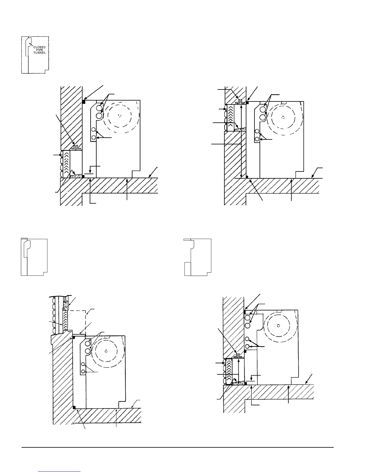
Figure 11 – The 21
7
/
8
” (556mm) Deep Full Adapter Back Unit with Closed Pipe
Tunnel, Ducted with Top Intake
Figure 12 – 21
7
/
8
" (556mm) Deep Partial Adapter Back Unit with Open Pipe
Tunnel
Intake Louver
Not More
Than 12"
Unit Configuration Type AP
Unit Configuration Type AK
Figure 9 - 21
7
⁄
8
" (556mm) Deep Full Adapter Back Unit With Standard Louver
Application
Figure 10 - 21
7
⁄
8
" (556mm) Deep Full Adapter Back Unit with High Louver
Application
Not More
Than 28"
(711mm)
Floor
Line
Unit Configuration Type AN
1"
(25mm)
Sealed Cement
Mortar;
Pitch Away
From Unit
Louver
Piping
Important: Gasket sealing
surface is required. (see figure
13 & 14 on page 7) Seal under
unit required.
Lintel
(By Others)
Piping
Floor
Line
Sealed Cement
Mortar;
Pitch Away
From Unit
Important: Gasket sealing
surface is required. (see figure
13 & 14 on page 7) Seal under
unit required.
Louver
Lintel
(By Others)
Piping
Piping
Important: Gasket sealing surface is required.
(see figure 13 & 14 on page 7) Seal under unit
required.
1"
(25mm)
Floor Line
Piping
Piping
Sealed Cement
Mortar;
Pitch Away
From Unit
Important: Gasket sealing
surface is required. (see figure
13 & 14 on page 7) Seal under
unit required.
Louver Installation With Typical Unit Configurations
Lintel
(By Others)
Gasket Seal
Gasket Seal
Floor Line
Gasket Seal
Gasket Seal
Intake Louver
Piping
Piping
Window Sash
“Goose Neck”
Insulated Duct (By Others)
Duct Collar (By AAF)
Note:
Arrangement AB with full metal back panel, similar to
configuration type AN. (Outside air opening to be cut and
sealed by others.)