18
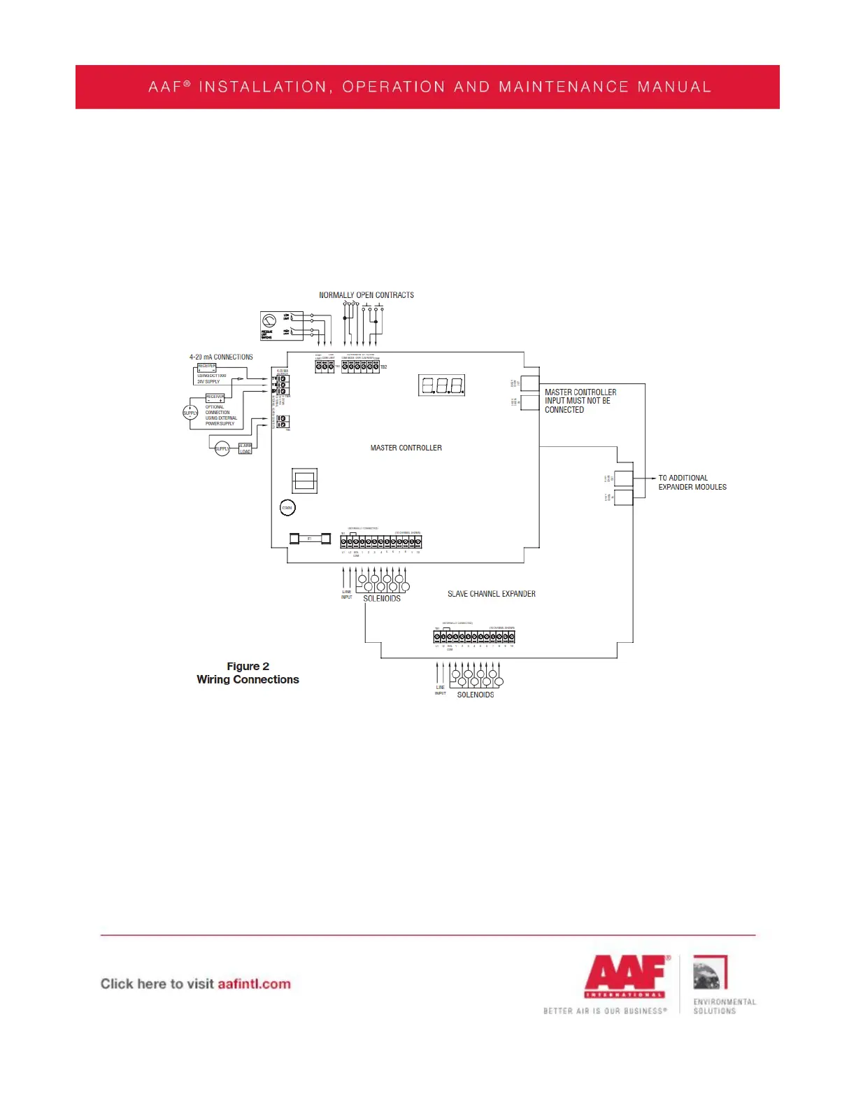
To power up the DCT controller, connect power line to L1 and L2. Control Wiring must
be field installed between the solenoid valves and the pulse output terminals as shown on
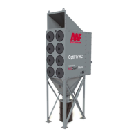
the electrical connection diagram that is supplied with the specific OptiFlo RC collector
ordered.
The power requirements are 85-270V/50-60Hz/1Ph. The operating temperature
range is -40F to 140F.
Continuous cleaning operations do not require external inputs and can be used for
time based cleaning by placing a jumper wire across the manual override and common, or
across the high limit input and common.