...
. . . . .
·1·iil·I··
ii II ii
AALBORG
INDUSTRIES
2
21-20/60
, '
OIL/AIR
REGULATIONI
OM5560_95#A.2
I ,
The air quantity
is
matched to the fired oil quantity by means
of
the control system,
which controls the servomotor for the air dampers.
Servomotor
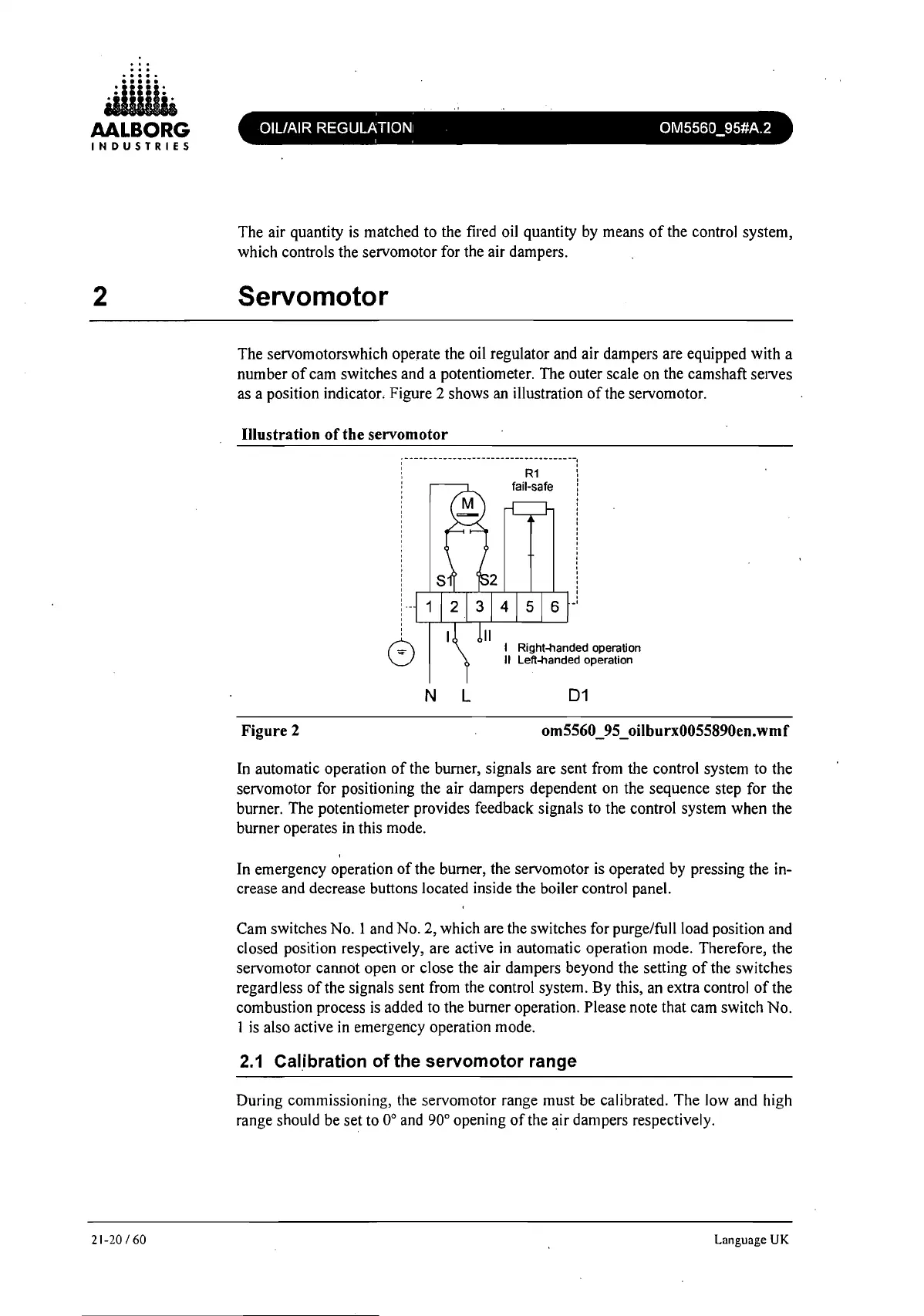
The servomotorswhich operate the oil regulator and air dampers are equipped with a
number
of
cam switches and a potentiometer. The outer scale on the camshaft serves
as a position indicator. Figure 2 shows an illustration
of
the servomotor.
Illustration
of
the servomotor
; -
----
--
----
----
----
--------
-------
--I
, '
, '
, '
: :
, '
, '
I 1
,
,
,
,
,
,
,
,
,
,
,
,
,
,
r-"--.--'--r-'-...-''--r-'-,-L-,
!
N
L
-,
I Right-handed operation
II
Left-handed operation
D1
Figure 2 om5560_95_oilburx0055890en.wmf
In automatic operation
of
the burner, signals are sent from the control system to the
servomotor for positioning the air dampers dependent on the sequence step for the
burner. The potentiometer provides feedback signals to the control system when the
burner operates in this mode.
In emergency operation
of
the burner, the servomotor
is
operated by pressing the in-
crease and decrease buttons located inside the boiler control panel.
Cam switches No. I and
No.2,
which are the switches for purge/full load position and
closed position respectively, are active in automatic operation mode. Therefore, the
servomotor cannot open or close the air dampers beyond the setting
of
the switches
regardless
of
the signals sent from the control system. By this, an extra control
of
the
combustion process
is
added to the burner operation. Please note that cam switch No.
1
is
also active
in
emergency operation mode.
2.1
CaUbration
of
the
servomotor
range
During commissioning, the servomotor range must be calibrated. The low and high
range should be set to
0°
and 90° opening
of
the air dampers respectively.
Language
UK
 Loading...