Name
1 SETPOINT input connector 6 Optional analog 4-20 mA output terminal block
2 CONTROL I/O connector 7 AC power input terminal block
3
SER.OUT
(Standard serial output) connector
8 Protective conductor terminal
4 Option slot 9 Slide rail
5 Load cell input terminal block
2.3.
Accessories
Name Qty. Name Qty.
Terminal block cover 1 Panel mount packing 1
Terminal block cover securing screw 2 Rubber foot 4
Connector for the CONTROL I/O 1 Rating label 1
Connector for the SER.OUT 1 Status label 1
3. INSTALLATION TO CONTROL PANEL
Make a hole in a control panel as shown below.
Unit: mm
Remove the slide rails on both sides and
insert the AD-4401A with the accessory
packing through the hole into the panel.
Insert the slide rails from behind.
AD-4401A
Weighing Indicator
Simplified Instruction Manual
This manual is a simplified version of the instruction manual.
When using the indicator, please read the AD-4401A Weighing
Indicator Instruction Manual which is available on our website.
Download the latest complete instruction manual at:
URL: http://www.aandd.co.jp/
No part of this publication may be reproduced, transmitted,
transcribed, or translated into any other language in any form by any
means without the written permission of A&D Company, Limited.
The contents of this manual and the specifications of the instrument
covered by this manual are subject to change for improvement without
notice.
2015 All rights reserved.
3-23-14 Higashi-Ikebukuro, Toshima-ku, Tokyo 170-0013, JAPAN
Telephone: [81] (3) 5391-6132
Fax: [81] (3) 5391-6148
1WMPD4003052
1. SAFETY PRECAUTIONS
Read the following precautions carefully before using the indicator.
[Precautions for designing]
WARNING
● Provide an external safety circuit to the indicator so that the safety of the whole system
can be secured even if errors occur in the external power supply or in the indicator.
[Precautions for installation]
WARNING
● Do not use the indicator in the following environments:
- where the temperature and the humidity exceed the specifications
- where corrosive gases or flammable gases exist
- where the indicator gets wet with oil, chemicals or water
Please note that securing the indicator to the control panel will provide the
indicator outside of the control panel with IP65 protection.
● When installing or removing the indicator, be sure to turn off all used external
power supplies beforehand.
[Precautions for wiring]
WARNING
● When wiring the indicator, be sure to turn off all used external power supplies
beforehand.
● When wiring is complete, be sure to attach the terminal block cover provided
with the indicator.
● Be sure to earth ground the indicator.
CAUTION
● Do not clamp control wires or communication cables with power lines or place
them close to power lines.
● Place the load cell cable sufficiently away from high frequency circuits such as
high voltage power lines and inverter load circuits.
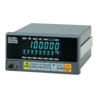
2. PART NAMES
2.1.
Front Panel
6.2.
Calibration Using Calibration Weights
Press the CAL key in the normal mode.
When “
Cal" is displayed, press the ENTER key.
When “
Cal 5et” is displayed, press the ENTER
key.
Zero calibration
Press the ENTER key when the STABLE (MD)
status is turned OFF.
When the Function key is pressed, the AD-4401A
proceeds to span calibration without performing
zero calibration.
Dashes are displayed in the sub-display and zero
calibration is performed.
Span calibration
Set the calibration weight value in the sub-display.
Press the ENTER key when the STABLE (MD)
status is turned OFF.
Dashes are displayed in the sub-display and span
calibration is performed.
Press the ON/OFF key twice to return to the normal
mode.
7. FUNCTIONS
When the AD-4401A is powered ON, all the segments of the display turn ON and OFF
to check the display. Then the AD-4401A enters the normal mode and starts weighing.
If the AD-4401A is powered OFF during the OFF mode (with the display OFF),
the AD-4401A will be in the OFF mode when powered ON.
7.1.
Control I/O
The applicable connector is an FCN-360 series 16-pin female connector
manufactured by Fujitsu Component Limited or the equivalent. An FCN-361J016
(connector) and an FCN-360C016 (cover) are provided with the indicator.
Pin No. Description Description Pin No.
A1 Zero setting Input Near-zero Output B1
A2 Tare Input Underweight, Hi-Hi Output B2
A3 Weighing start Input OK, Hi Output B3
A4 Emergency stop Input Large flow, Full, Go Output B4
A5 Discharge start Input Medium flow, Lo Output B5
A6 Key lock Input Small flow, Lo-Lo Output B6
A7 Input common Discharge Output B7
A8 Output common Weighing end Output B8
The above are the default settings. Assigned functions can be changed for each pin.