2
NOTENOTE
NOTENOTE
NOTE: Some 5000 and 7000 Model Awning torsion
assemblies can not be pinned. If you have this type, the
torsion spring must be unwound before the awning can
be removed from the coach. Follow the instructions in
Section C, Steps 1 and 2.
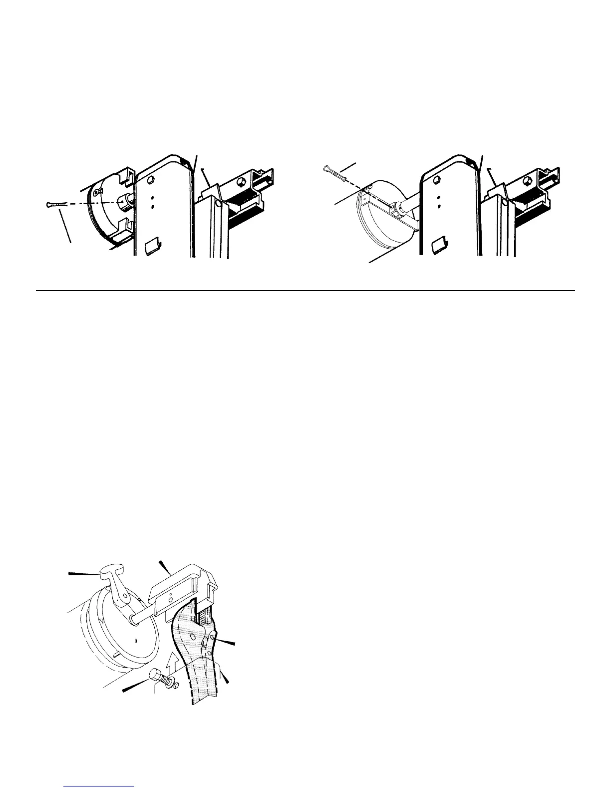
b. To keep the 5000 or 7000 Model Awning from unwind-
ing, it must be pinned. See FIGS. 3 & 3A.
C.C.
C.C.
C.
UNWINDING A UNWINDING A
UNWINDING A UNWINDING A
UNWINDING A
TT
TT
T
ORSION ASSEMBLORSION ASSEMBL
ORSION ASSEMBLORSION ASSEMBL
ORSION ASSEMBL
Y SPRINGY SPRING
Y SPRINGY SPRING
Y SPRING
NOTENOTE
NOTENOTE
NOTE: If the awning is installed on a coach, complete the
following steps on a step ladder, with the awning fabric
unrolled two feet from the awning rail.
1. Clamp a Vise Grip® tightly on the top casting. Remove
the 1/4-20 hex head machine screw from the top
casting. See FIG. 4.
WW
WW
W
ARNINGARNING
ARNINGARNING
ARNING
Severe injuries can result from the rapid spin-off ofSevere injuries can result from the rapid spin-off of
Severe injuries can result from the rapid spin-off ofSevere injuries can result from the rapid spin-off of
Severe injuries can result from the rapid spin-off of
the top casting. Use Vise Gripsthe top casting. Use Vise Grips
the top casting. Use Vise Gripsthe top casting. Use Vise Grips
the top casting. Use Vise Grips®
- -
- -
-
NEVERNEVER
NEVERNEVER
NEVER
use bare use bare
use bare use bare
use bare
hands - to handle a top casting under springhands - to handle a top casting under spring
hands - to handle a top casting under springhands - to handle a top casting under spring
hands - to handle a top casting under spring
tension.tension.
tension.tension.
tension.
2. Take the top casting carefully out of the main support
arm (see NOTE below). Slowly let the torsion spring
unwind completely. Repeat Steps 1 & 2 for the opposite
end.
NOTENOTE
NOTENOTE
NOTE: If the awning's right-hand torsion assembly has
been pinned (5000 & 7000 Models), the cotter pin must be
removed from the torsion assembly before the spring can
be unwound. If the awning is an 8000, 8500, 9000, 9500 or
Grande Pavilion Model, the cam lock lever on the right-
hand torsion assembly must be turned clockwise to the roll
up position, before the spring can be unwound.
MAIN SUPPORT ARM
LOCKING
TAB
FIG. 3A
7000 MODEL AWNING7000 MODEL AWNING
7000 MODEL AWNING7000 MODEL AWNING
7000 MODEL AWNINGFIG. 3
5000 MODEL AWNING5000 MODEL AWNING
5000 MODEL AWNING5000 MODEL AWNING
5000 MODEL AWNING
COTTER PIN
MAIN SUPPORT ARM
LOCKING
TAB
COTTER PIN
LOCK
LEVER
TOP
CASTING
MAIN SUPPORT
ARM ASSEMBLY
VISE-
GRIPS®
1/4-20 X 1/2" HEX
HD. MACH. SET SCREW
FIG. 4
 Loading...