5
Figures:
Figure 1 - Lockable Handle .......................................................................................................... 19
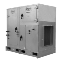
Figure 2 - SB Series ...................................................................................................................... 21
Figure 3 - SB Series Unit Orientation ........................................................................................... 22
Figure 4 - SB Schematic with (1) Exhaust Fan, (2) Energy Recovery, (3) Air Handler, and (4)
Compressor Section ...................................................................................................................... 23
Figure 5 - Connect Sections .......................................................................................................... 23
Figure 6 - Bar Clamp .................................................................................................................... 23
Figure 7 - Flange Overlap ............................................................................................................. 23
Figure 8 - Self-Tapping Screw ...................................................................................................... 23
Figure 9 - Strap Types................................................................................................................... 24
Figure 10 - Low Voltage Quick Connect ...................................................................................... 24
Figure 11 - Ship Split sections ...................................................................................................... 25
Figure 12- Water Connections for Water-Source Heat Pumps ..................................................... 28
Figure 13 - Electrical Connection ................................................................................................. 30
Figure 14 - Drain Trap .................................................................................................................. 33
Figure 15 - Energy Recovery Wheel ............................................................................................ 36
Figure 16 - Cross Section of Air Seal Structure ........................................................................... 37
Figure 17 - Lifting Hole Locations ............................................................................................... 38
Figure 18 - Diameter Seal Adjustment ......................................................................................... 40
Figure 19 - Avoid Racking of Cassette Frame.............................................................................. 41
Figure 20 - Diameter Seal Adjustment ......................................................................................... 42
Figure 21 - Hub Seal Adjustment ................................................................................................. 42
Figure 22 - Segment Retainer ....................................................................................................... 42
Figure 23 - Segment Installation ................................................................................................... 43
Figure 24 - Belt Replacement ....................................................................................................... 44
Figure 25 - Typical wiring diagram with EC motor ..................................................................... 45
Figure 26 - Shows the jumper that is to be removed (jumped between S1 and S2). .................... 45
G149170 · Rev. B · 240515
(LV J000301)
 Loading...