Page 4 American Access Systems / Security Brands, Inc.
STEP 1-MOUNTING THE UNIT
Page 3 tells you what tools and instruments you will need to install your unit and presents a parts check list. Make sure
to have all the tools listed. Upon opening the box, check off the items enclosed with the unit. If any items are missing
from your unit, contact American Access Systems immediately.
Mounting the unit to your own pedestal
Your unit comes with a square mounting ange found in the bottom of the box along with four carriage bolts and four
hex nuts. The square mounting ange may be welded to your pedestal and the ange bolt pattern will align with the
back of the unit. Place the unit up to the ange and insert the carriage bolts from the back side. Secure the unit to
the ange by tightening down the hex nuts with a 7/16” socket.
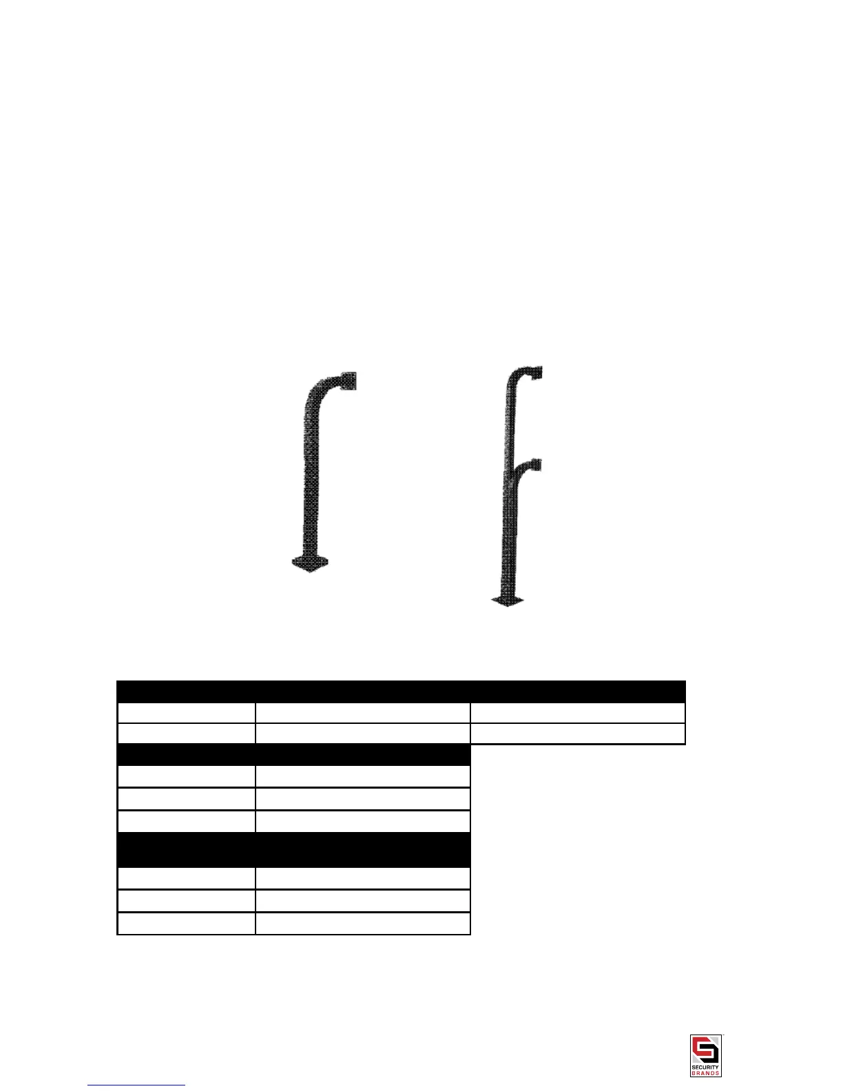
Mounting the unit to an AAS gooseneck (18001) or double height (18003)pedestal
Locate the four carriage bolts and four hex nuts found inside the unit box. Place the unit up to the pedestal ange
and insert the four carriage bolts from the backside. Secure the unit to the pedestal using the four hex nuts and a
7/16” socket. The extra square mounting ange may be discarded.
Mounting the unit to an AAS diagonal pedestal (18002)
Locate the four bolts provided with the pedestal. Place the unit up to the pedestal so that the unit hole pattern aligns
with the pretapped pedestal bolt holes. Insert the pedestal bolts from the inside of the unit and tighten down with a
7/16” socket. The extra square mounting ange, four carriage bolts, and four hex nuts provided inside the unit box
may be discarded.
STEP 2-SYSTEM CONNECTIONS
Study the WIRING COLOR CODE chart below and then proceed to the hookup steps.
ACU HARNESS COLOR CODES
RED (+) POSITIVE 6-12 volts DC
BLACK (-) NEGATIVE Common
LATCH CONTACTS
BROWN RELAY COMMON
ORANGE NORMALLY OPEN
BLUE NORMALLY CLOSED
SHUNT CONTACTS
(Used for external alarm)
GRAY RELAY COMMON
VIOLET NORMALLY OPEN
YELLOW NORMALLY CLOSED
 Loading...