EasyManua.ls Logo

AB Quality 1794-IB16 User Manual

AB Quality 1794-IB16
16 pages
To Next Page IconTo Next Page
Page #1 background imageLoading...
Page #1 background image
  " #!!
 % $# # 
$#  & # ! 
   

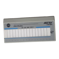
(Cat. No. 1794-IB16)
 
This module mounts on a 1794 terminal base unit.
1. Rotate keyswitch (1) on terminal base unit (2) clockwise to position 2
as required for this type of module.
2. Make certain the flexbus connector (3) is pushed all the way to the left
to connect with the neighboring terminal base/adapter. You cannot
install the module unless the connector is fully extended.
3. Make sure that the pins on the bottom of the module are straight so
they will align properly with the connector in the terminal base unit.
WARNING
!
If you remove or insert the module while the
backplane power is on, an electrical arc can occur.
This could cause an explosion in hazardous location
installations. Be sure that power is removed or the
area is nonhazardous before proceeding.
4. Position the module (4) with its alignment bar (5) aligned with the
groove (6) on the terminal base.
5. Press firmly and evenly to seat the module in the terminal base unit.
The module is seated when the latching mechanism (7) is locked into
the module.
Installation Instructions
Question and Answer IconNeed help?

Do you have a question about the AB Quality 1794-IB16 and is the answer not in the manual?

AB Quality 1794-IB16 Specifications

General IconGeneral
ManufacturerAllen-Bradley
Product TypeDigital Input Module
Input Channels16
Input TypeDC Sink/Source
Point Delay Time - Off to On1ms max
Point Delay Time - On to Off1ms max
Isolation Voltage500V AC
Series1794
CompatibilityFLEX I/O
CommunicationVia Backplane
Operating Temperature-20 to 70 °C (-4 to 158 °F)
Dimensions94 x 94 x 69 mm
Dimensions (inches)3.7 x 3.7 x 2.7 inches

Summary

Module Installation

Important User Information

Environment and Enclosure

Preventing Electrostatic Discharge

Wiring to Terminal Base Unit

Indicators Overview

Memory Map

Setting Input Filter Time

Hazardous Location Operation

Product Specifications

General Specifications

Details electrical, dimensional, and environmental operating parameters.

Input Filter Time Specifications

Defines available input filter time settings for the module.

Flexbus and Power Specifications

Covers Flexbus current, power, and thermal dissipation ratings.

Indicator and Keyswitch Specifications

Details status indicator types and keyswitch position.

Environmental and Immunity Specifications

Storage and Operating Conditions

Specifies storage temperature, humidity, shock, and vibration ratings.

Electromagnetic Compatibility

Details ESD, RF, EFT/B, and surge immunity, plus emissions.

Agency and Zone Certifications

Agency Certifications

Lists UL, CSA, EEx2, CE2, and C-Tick certifications.

European Zone 2 Certification

Details compliance for use in potentially explosive atmospheres.

Additional Zone 2 Requirements

Derating Curve