Wiring with the logic relay
104
1SVC 440 795 M0100
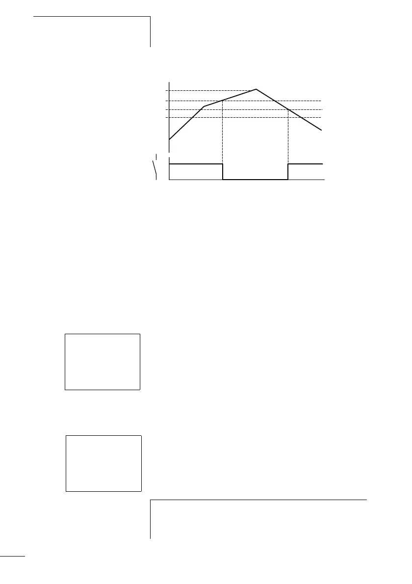
Figure 48: Signal diagram of analog value comparator in Less than
mode
1: actual value at I7
2: setpoint plus hysteresis value
3: setpoint
4: setpoint minus hysteresis
The n/o contact switches off when the actual value at I7
exceeds the setpoint plus hysteresis. If the actual value at I7
falls below the setpoint, the n/o contact switches on.
Function of the Less than/equal to comparison
Parameter display and parameter set for Less than/equal to
analog value comparator.
Circuit diagram with analog value comparator.
on
off
1
2
3
4
A2 LE +
I1 I7 Æ
F1 +0
I2 0100 æ
F2 +0
OS +0
HY 0025
A2-------ÄQ1
h
The values F1 +0, F2 +0 and OS +0 were not defined.
No values are used with a gain factor, and no offset is
used.
 Loading...


