Wiring with the logic relay
126
1SVC 440 795 M0100
You integrate a high-speed counter into your circuit in the
form of a contact and coil.
.The coils and contacts have the following meanings:
Parameter display and parameter set for the
high-speed counter:
In the parameter display of a counter relay you change the
mode, the setpoint and the enable of the parameter display.
h
If you use C13 or C14 as high-speed counters you must
enable them with the coil CC13 or CC14 accordingly.
---------CC
13
C
13
-------SN3
I6-------DC
13
I8-C
13
----RC
13
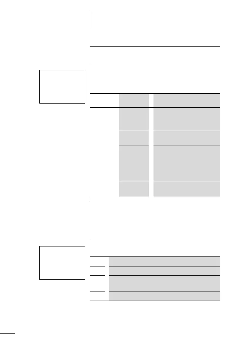
Contact Coil
C13 to
C14
The contact switches if the
actual value is greater than or
equal to the setpoint.
CC13, CC14 Enable of the high-speed
counter on 1 signal coil activated
DC13, DC14 Counting direction
• Status 0, not activated, up
counting.
• Status 1, activated, down
counting.
RC13, RC14 Reset, coil triggered: actual
value reset to 00000
h
The high-speed counter can also be enabled specifically
for a special operating state. This has the advantage that
the cycle time of the device is only burdened with the
counting when it is taking place. If the high-speed counter
is not enabled, the cycle time of the device is shorter.
C
13
H+
S 00950
C13 Counter function relay number 13
H High-speed counter mode (H = high speed)
+ • + appears in the PARAMETER menu.
• - does not appear in the PARAMETER menu
S Setpoint, constant from 00000 to 32000
 Loading...


