4
English
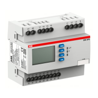
I Front view with operating controls
햲
Indication of operational states with LEDs
U: LED red - Status indication of the measured
voltage
Switch position
d -
V
overvoltage
Switch position
c -
W
undervoltage
R: LED yellow - Status indication of the output relays
V
energized
U/T: LED green - Status indication of control supply
voltage and timing
V
Control supply voltage
applied
W
Tripping delay T
v
active
햳
Adjustment of the release threshold (hysteresis)
햴
Adjustment of the threshold value
햵
Adjustment of the measuring range
(3-30 V; 6-60 V; 30-300 V; 60-600 V AC/DC)
햶
Adjustment of the tripping delay T
v
(0 s; 0,1-30 s)
Attention:
When compared with our previous version, the position of
the adjustment potentiometers 햵 and 햶 have changed
places!
II DIP switch functions
햷
DIP switches for the adjustment of:
1 ON = Undervoltage monitoring
OFF =
Overvoltage monitoring
2 No function
Default setting:
All DIP switches in position OFF
III DIP switch position
IV Connection diagram
A1-A2 Control supply voltage U
s
B-C Measured voltage
11(15)-12(16)/14(18) Output relay 1
21(25)-22(26)/24(28) Output relay 2
Français
I Face avant et dispositifs de commande
햲
Indication de fonctionnement par LED
U: LED rouge - Indication de la tension de mesure
Position de l’interrupteur
d -
V
surtension
Position de l’interrupteur
c -
W
sous-tension
R: LED jaune - Indication de l’état des relais de sortie
V
activés
U/T: LED verte - Indication de la tension d’alimentation
de commande et temporisation
V
Tension d‘alimentation de
commande appliquée
W
Temporisation de
déclenche ment T
v
active
햳
Réglage de l‘hystérésis
햴
Réglage de la valeur de seuil
햵
Réglage de la gamme de mesure
(3-30 V; 6-60 V; 30-300 V; 60-600 V AC/DC)
햶
Réglage de la temporisation de déclenchement T
v
(0 s; 0,1-30 s)
Attention:
En comparaison à la version précédente, la position des
potentiomètres de réglage 햵 et 햶 a été intervertie!
II Fonctions des micro-interrupteurs
햷
Micro-interrupteurs pour le réglage de:
1 ON = Contrôle de sous-tension
OFF =
Contrôle de surtension
2 Pas de fonction
Etat de livraison:
Tous les micro-interrupteurs en position OFF
III Position des micro-interrupteurs
IV Schéma de connexion
A1-A2 Tension d‘alimentation de
commande U
s
B-C Tension de mesure
11(15)-12(16)/14(18)
Relais de sortie 1
21(25)-22(26)/24(28)
Relais de sortie 2