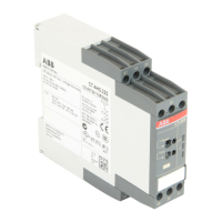
I Front view with operating controls
a
Adjustment of the time range (depending on the device)
by selecting the max. value of the desired time range:
Time range: Yellow scale:
0.15 - 3 s = 3 s
1.5 - 30 s = 30 s
15 - 300 s = 300 s
1.5 - 30 min = 30 m
15 - 300 min = 300 m
1.5 - 30 h = 30 h
15 - 300 h = 300 h
Time range: White scale:
0.05 - 1 s = 1 s
0.5 - 10 s = 10 s
5 - 100 s = 100 s
0.5 - 10 min = 10 m
b
Direct reading scale to set the time value within the
chosen range
- Yellow scale: 1.5 - 30
- White scale: 0.5 - 10
If the value on the scale “T Range” is yellow
→ use yellow time values on the scale “Time”
If the value on the scale “T Range” is white
→ use white time values on the scale “Time”
Calculation of the time value:
“T Range” Value on scale “Time”
1 s, 3 s → x 0.1 = Time value
10 s, 30 s, 10 m, 30 m, 30 h → x 1 = Time value
100 s, 300 s, 300 m, 300 h → x 10 = Time value
Example 1:
Time value to set: 0.2 s
Select 3 s on yellow scale “T Range”
Select 2 on yellow scale “Time”
2 x 0.1 = 0.2 s
Example 2:
Time value to set: 80 s
Select 100 s on white scale “T Range”
Select 8 on white scale “Time”
8 x 10 = 80 s
c
Function on CT-AHS, CT-ARS, CT-APS, CT-ERS /
Selection of the function on CT-MBS, CT-MFS, CT-MVS,
CT-WBS
Functions: see III
d
Setting of the 2nd c/o contact as an instantaneous
contact
Position Inst. “I”: Instantaneous contact
e
Indication of operational states with LEDs
U/T: green
LED
- Status indication of control supply
voltage and timing
V
Control supply voltage
applied
W
Time delay is running
(not on CT-ARS)
R: yellow LED - Status indication of output relay
V
energized
R1/R2: yellow LED
- Status indication of output relays
1 and 2
V
energized
f
Selection of the function on CT-MXS
1 ON = Single pulse generator, starting with OFF
2 ON = ON-delay and OFF-delay, asymmetrical
3 ON = Impulse-ON and impulse-OFF
4 ON = No function
All ON = ON/OFF-function
All OFF = Pulse generator, starting with ON or OFF
Default setting:
All DIP switches in position OFF
II Electrical connection
For the rated control supply voltage and the
circuit diagram, see label at the side of the unit.
A1-A2 Control supply voltage Us
A1-Y1/B1 Control input to start timing
(voltage-related triggering)
Y1-Z2 Control input to start timing
(voltage-free triggering)
X1-Z2 Control input to pause timing / accumulative
function (see function diagram 19)
Z1-Z2 Remote potentiometer connection for the fine
adjustment of the time delay. When an external
potentiometer is connected, the internal, front-
face potentiometer is disabled.
Z2-Z3/Z1 1st/2nd remote potentiometer connection for
the fine adjustment of the time delay.
When an external potentiometer is connected, the
corresponding internal, front-face potentiometer
is disabled.
15-16/18 1st c/o contact
25-26/28 2nd c/o contact
21-22/24 2nd c/o contact, set as instantaneous contact
17-18 1st n/o contact
17-28 2nd n/o contact
CT-ARS:
Prior to first commissioning and after a storage time of more
than 6 months without any voltage, a formatting time of about
5 minutes is necessary!
Only after applying control supply voltage for the first time, the
output contacts will take their correct switching position.
English
Page 13/25

 Loading...