41-201.4H CV Voltage Relay Class 1E
4
3.2.2. Trip Circuit
The main contacts will close 30 amperes at 250 volts
dc and the seal-in contacts of the indicating contactor
switch will carry this current long enough to trip a cir-
cuit breaker.
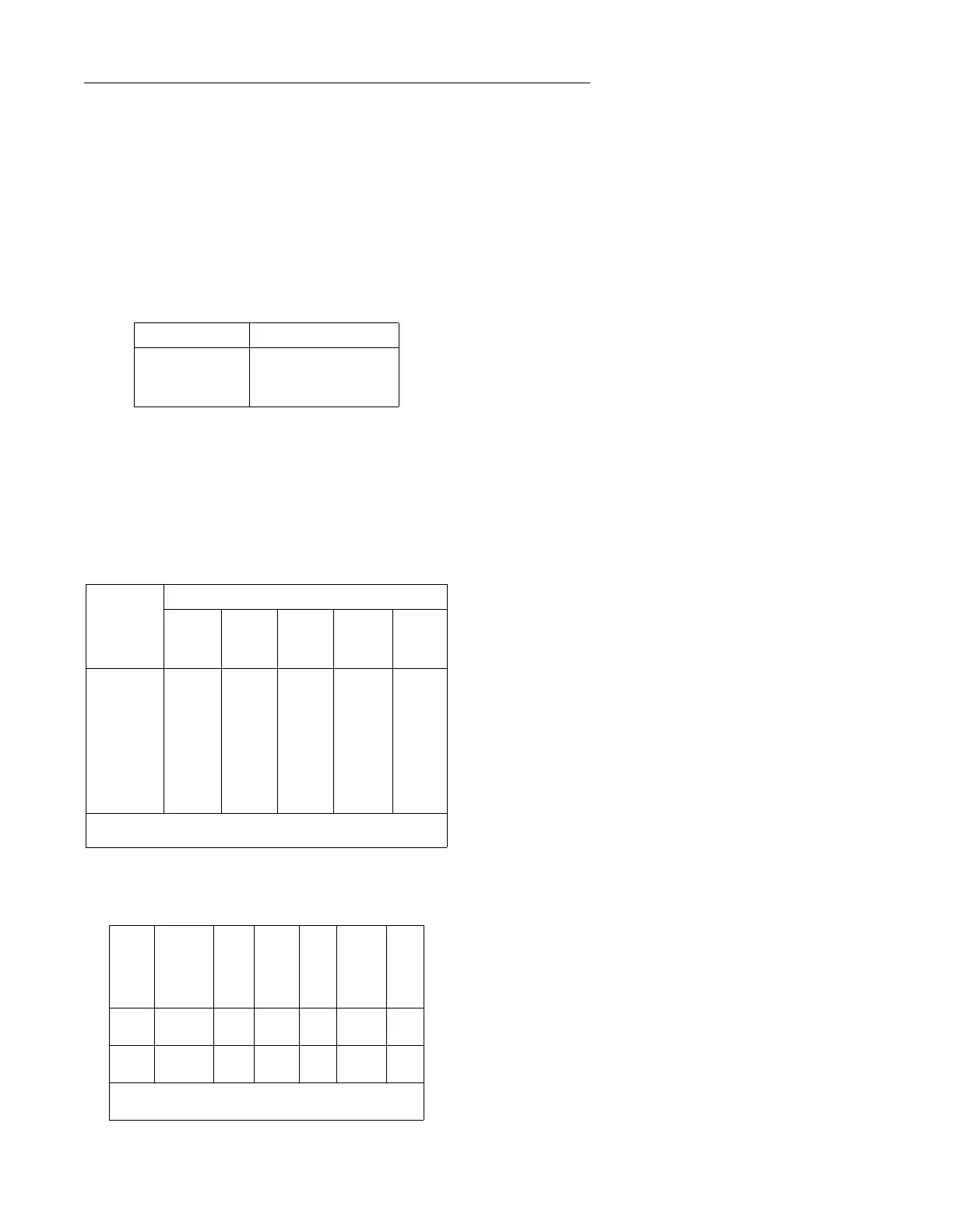
3.2.3. Trip Circuit Constants
Indicating Contactor Switch Coil, or Indicator Coil.
3.3. ENERGY REQUIREMENTS
The 60 Hz burdens of the CV-1, CV-2, CV-4, CV-5,
CV-6, CV-7 relays at rated voltage are as follows:
(For 50 Hz, multiply volt-amperes by 1.18, multiply
watts by 1.38.)
The 50 Hz and 60 Hz burdens of the CV-8 relays at
continuous voltage do not exceed the following:
4.0 SETTINGS
4.1. CV UNIT
The setting of the CV unit can be defined either by tap
setting and time dial position or by tap setting and a spe-
cific time of operation at some percentage of tap value
voltage (e.g. on CV-4 120 tap setting, 2 time dial position
or 120 tap setting, 12 seconds at 140 percent of tap
value voltage).
To provide selective circuit breaker operation, a minimum
coordinating time of 0.3 seconds plus circuit breaker time
is recommended between the relay being set and the
relays with which coordination is to be effected.
The nylon screw on the terminal plate holds the tap
plate in position when taps are being changed. To
use the position on the terminal plate in which the
nylon screw is used, remove the nylon screw and
place it in one of the unused holes. Then remove the
tap screw and insert it in the terminal plate hole.
4.2. CV-8 SETTINGS
The CV-8 relay has no taps. Its minimum pickup of
approximately 8% of continuous voltage is set by
adjusting the restraint spring. For this setting, the
adjustable resistor, where used, should be shorted out.
Where the resistor is used, the pickup setting can be
adjusted from approximately 8% to 30% of the continu-
ous voltage rating. This setting is made by adjusting the
resistor. Note, however, that the CV-8 time curves
shown in Figure 11 (page 13) apply only when the
resistor is shorted out. Timing tests should be con-
ducted after the resistor is used to change the pickup.
This will verify proper coordination time for the desired
pickup setting. Figure 12 (page 14) shows operate time
when the resistor is set for maximum pickup.
4.3. INSTANTANEOUS RECLOSING
The factory adjustment of the voltage unit contacts
provides a contact follow. Where circuit breaker reclos-
ing will be initiated immediately after a trip by the over
voltage contact, the time of the opening of the contacts
should be a minimum. This condition is obtained by
loosening the stationary contact mounting screw,
removing the contact plate and then replacing the
plate with the bent end resting against the contact
spring.
Ampere Pickup Ohms dc Resistance
0.2
1.0
2.0
8.5
0.37
0.10
Rated ∆
Voltage
Taps
120
Volt
Relay
240
Volt
Relay
Volt-
Amps
Power
Factor Watts
120 or
240 Volts
55
64
70
82
93
105
120
140
110
128
140
164
186
210
240
280
10.0
7.0
5.8
4.0
3.1
2.4
1.8
1.3
.38
.35
.34
.33
.31
.29
.28
.26
3.8
2.5
2.0
1.3
1.0
.7
.5
.3
∆ These relays will continuously withstand either 110% of rated volt-
age or tap value voltage, whichever is higher.
Continuous
Voltage
Range
Setting
Applied
Voltage
VA
Power
Factor
Watts
67 5.4 to
20V
5.4
20
67
67
30
15
.342 10
199 16 to
40V
16
40
199
199
30
20
.342 10
The CV-8 short time (15 seconds) rating is 240V and
510V respectively for the 67 and 199V relays.