Operation Manual / TPS44-F.. - TPS61-F..
Installing the turbocharger
Page 88
April 2015 HZTL2412_EN Revision E
Installing the turbocharger
7.4
Remove covers from oil connections.
Visually inspect O-ring seals of oil supply and drain pipe (O-ring seals
for engine are not delivered by ABB Turbo Systems).
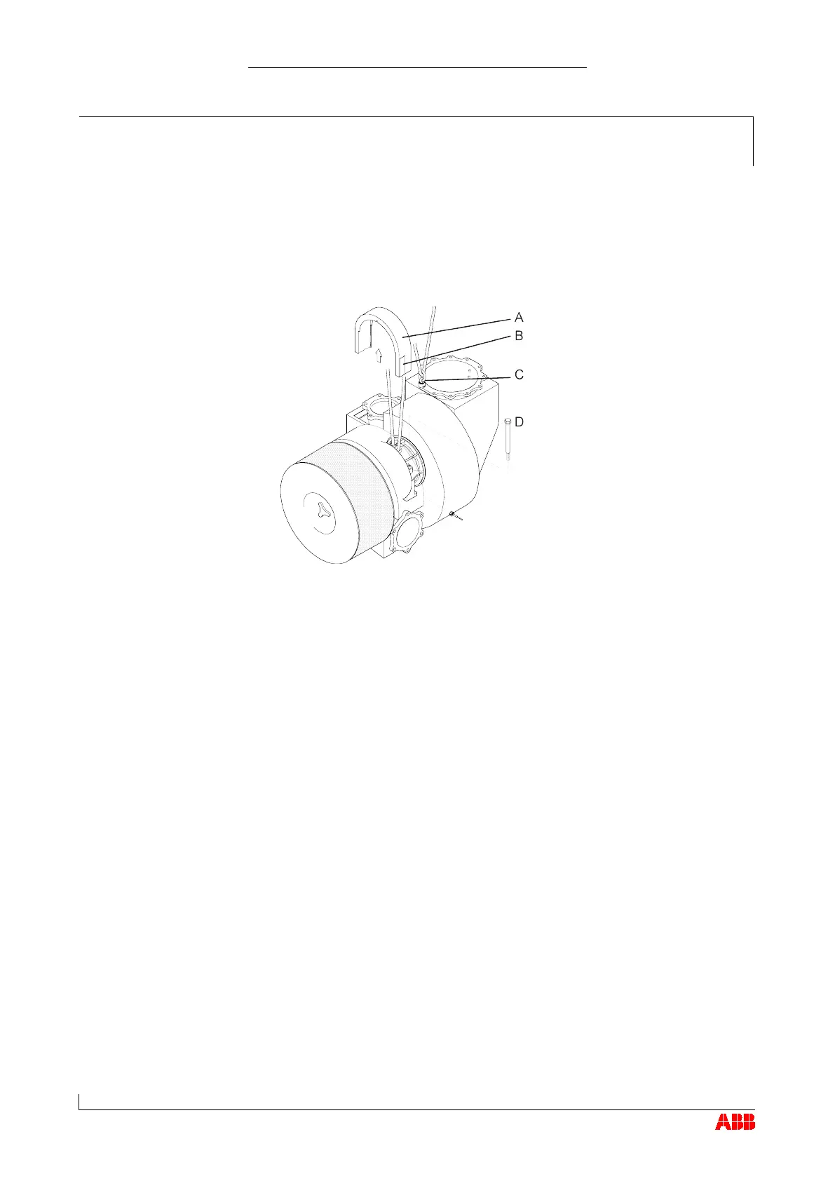
Fasten lifting gear to bearing casing.
If a gas outlet manifold is provided, sling lifting gear around it
additionally or fasten it to lifting gear using a swivel lifting eye (C). (See
also section Transport / Weights.)
Adapt turbocharger to suit engine.
Tighten fixing screws (D) on bearing casing.
Plug in cable connector of speed sensor and variable compressor
intake (VCI).
If provided, fasten hard insulation as follows:
Adapt bearing casing insulation to suit.
Tighten screws of bearing casing insulation (A).
Adapt screws and plate (B) of bearing casing insulation to suit.
Fasten all exhaust gas and air lines in accordance with engine
builder’s instructions.
Design with water-cooled bearing casing:
Remove screw plugs from water connections and fit water pipes in
accordance with engine builder's instructions.
© Copyright 2015 ABB. All rights reserved.