Operation Manual / TPL65-A32 / -A33 / -A36 + TPL69-A32 / -A33
9 Taking out of operation at short notice / 9.2 Locking the rotor
© Copyright 2020 . All rights reserved. HZTL2498_EN Rev.E March 2020
Locking rotor TPL65-A32 / A33 / A36
u Remove silencer or air suction branch.
NOTICE
Carry out the work as described in the chapter Disassembly and As-
sembly.
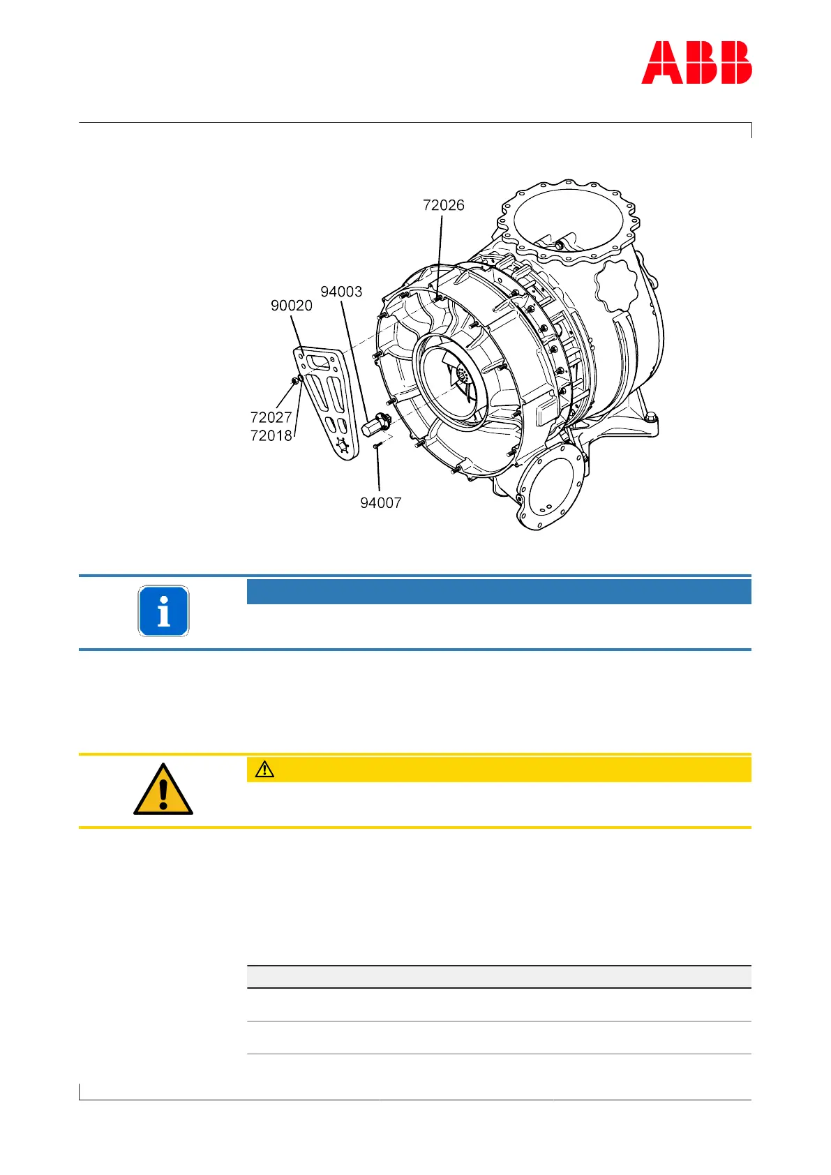
u Insert locking flange(94003) into compressor wheel.
u Position screws(94007) in unoccupied threaded holes of compressor
wheel and tighten them as specified in following Table of tightening
torques .
CAUTION
Do not remove any balancing screws from compressor wheel. Use only
unoccupied threaded holes to fit lifting spigot.
u Position assembly / disassembly device(90020) over studs(72026)
and locking flange(94003).
u Turn compressor wheel so that locking flange hexagon aligns with
hexagon in assembly / disassembly device(90020).
u Tighten nuts(74027) complete with washers(72018) on compressor
casing as specified in following Table of tightening torques.
Table of tightening
torques
Part number TPL65-A32 / -A33 / -A36
72027 M14
75Nm
94007 M8
25Nm
Page 100 / 118