Do you have a question about the ABB S900 and is the answer not in the manual?
Details legal notices, product compliance with directives, and registered trademarks.
Defines warning symbols, technical terms, abbreviations, and lists related ABB manuals.
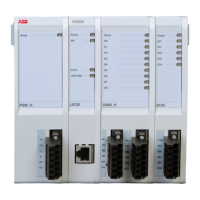
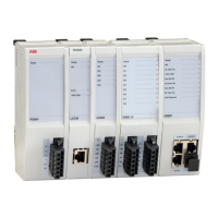
Details the S900 system, its components, explosion protection, and the CI920 interface's role.
Lists the types of I/O modules supported by the CI920, their descriptions, and software versions.
Lists essential hardware components and specifies PROFIBUS DP master requirements for full functionality.
Defines maximum stations/modules and explains factors influencing system response time.
Explains slave addressing conventions, setting the bus address, and the purpose/structure of GSD files.
Details GSD file structure, module description, language identifiers, and compatibility with specified GSD versions.
Details CIPB, CIPB C, CIPB D, and CIPB CD variants, their features, and supported modes.
Explains system behavior during cold start and Hot Configuration In Run (HCIR) for uninterrupted module changes.
Details parameters like mode, frequency, data format, and rack size for the communication interface.
Explains cyclic data transmission, input/output data, status, and non-cyclic DPV1 services.
Details C1/C2 access methods, multiple access management, and S900/DTM interaction.
Covers PROFIBUS diagnostics, including structure, header, station status, and module status.
Details redundant link establishment using two PROFIBUS cables for increased system availability.
Describes the passive reserve mode where the redundant CI920 has no valid address and is not accessed via PROFIBUS.
Explains LR_MODE1 operation and lists requirements for CI920 parameterization, addressing, and line isolation.
Defines switchover conditions to redundant CI920 and outlines diagnostics and behavior during module failure.
Details the meaning of the five LEDs on the CI920 front panel for indicating system status and errors.
Explains how the S900 reports diagnostic data to the master via the fieldbus and diagnostic buffer.
Explains telegram structure, header info, and bits within Station_status_1 for diagnostic reporting.
Explains the meaning of bits within Station_status_2 and Station_status_3 for diagnostic reporting.
Details octets containing the master address and manufacturer identifier for diagnostic purposes.
Describes the status bits for I/O modules indicating data validity, module errors, or missing modules.
Details the bit mapping per slot to indicate if a diagnostic message exists for the respective slot.
Details how channel errors are reported using bytes and specific error codes according to DP standard and S900.
Lists and explains specific error codes for CI920 and I/O modules, covering communication, power, and HART errors.
Provides an overview of project planning using GSD files, linking slaves to the bus, and configuring the station.
Describes parameterizing the S900 by editing user parameters when GSD file import is not supported.
Highlights slot settings influencing channels and details station layout definition and configuration importance.
Explains user parameters, their interpretation, and the division of parameter bytes into subsets.
Details using DTM for Symphony/Melody and configuring S900 with AC800M, noting diagnostic limitations.
Describes how S900 input values appear with status information and how it's processed by AC800M.
| Series | S900 |
|---|---|
| Manufacturer | ABB |
| Protection Class | IP20 |
| Input Voltage | 24 V DC |
| Number of Inputs | Varies by module |
| Number of Outputs | Varies by module |
| Communication Protocol | Profibus DP |