Controlled Switching — Buyer´s Guide
C-2
Edition 2, 2006-09
Application Introduction
When the capacitor bank is to be energized,
an input command is given to the Switch-
sync
TM
controller. Following the command,
the controller will determine a reference time
instant, related to the phase angle of the
busbar voltage. When this has been done,
and after an internally created waiting time,
the controller will then give an output closing
command to the circuit breaker. The time
instant for the output closing command is
determined by the make time of the circuit
breaker and the target point for making. Both
the predictable make time and target point
have been pre-programmed into the control-
ler. The circuit breaker will then make the
current at the correct time instant and mini-
mize the switching transients.
Suitable Circuit Breakers
ABB live tank circuit breakers and discon-
necting circuit breakers have spring operat-
ing mechanisms. For some of the variants, a
motor drive is incorporated as an alternative.
All these circuit breakers have stable operat-
ing times, which vary only to a limited extent
with factors such as ambient temperature
and control voltage. For moderate variation
of these factors, the opening and closing
times will typically show a variation of less
than plus/minus 0.5 ms. Similarly, after a long
idle time, either in closed or open position,
the circuit breakers will have stable operating
times, even upon the first operation.
The circuit breakers also have high and
stable dynamic dielectric withstand capabil-
ity between the contacts, both upon making
and breaking operations. These properties,
together with the stable operating times,
make these circuit breakers well suited for
controlled switching.
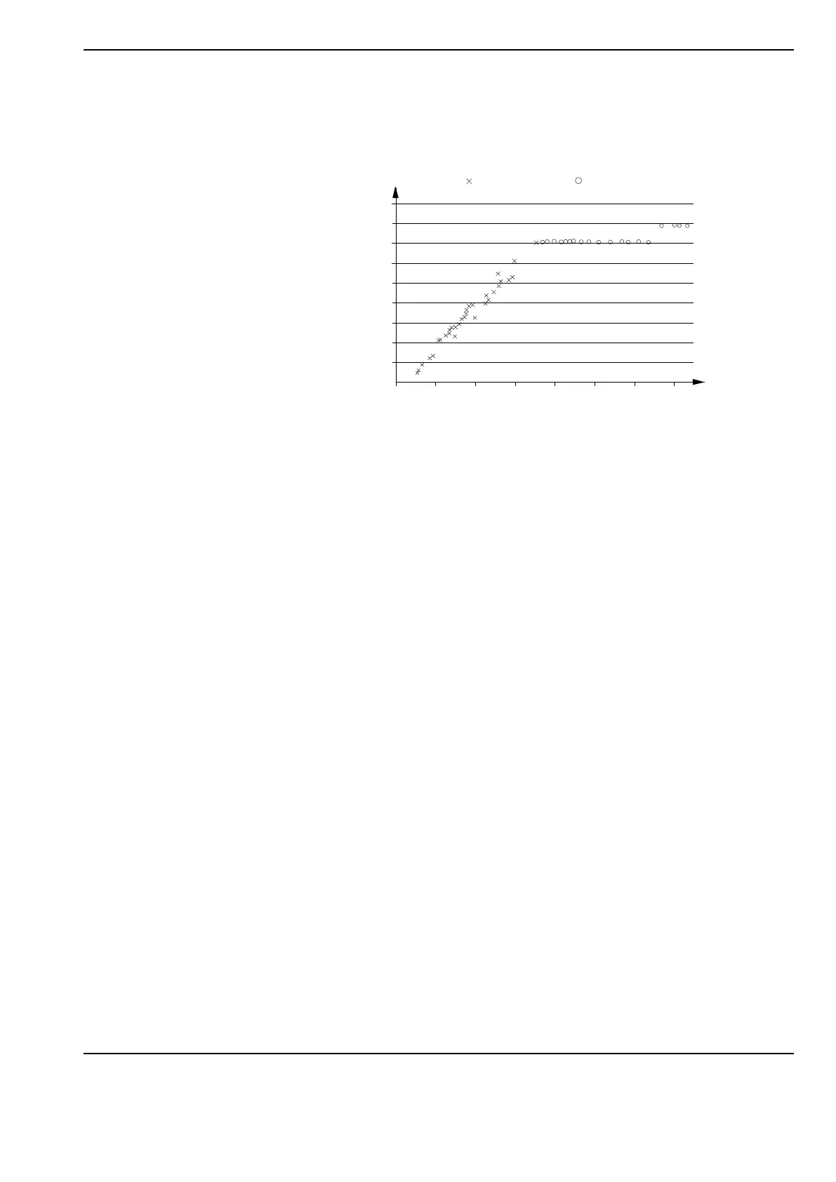
A typical example of measured RRDS (Rate
of Rise of Dielectric Strength) of a circuit
breaker is shown in figure below where x
points represent voltage breakdowns at a
certain time after contact separation and
The RRDS determination is done at no-
load opening operations by determining the
flashover limit at different contact distances
(times after contact separation) by applying a
rapidly increasing voltage at pre-determined
distances/times.
The no-load determined RRDS shall be
compared to results from shunt reactor in-
terruption tests to also verify that the arcing
gives no further reduction to the measured
RRDS. Based on experiences there is almost
no impact on the withstand performance
compared to the cold characteristics if the
interrupting current is in the range of some
hundreds of amps.
Since stable dynamic dielectric properties,
also having a high rate of change, are re-
quired for attaining successful performance
for controlled switching, it is not advisable
to combine pre-insertion resistors and con-
trolled closing.
The dynamic dielectric properties of the
pre-insertion resistor contacts are not steep
enough or stable enough to be suitable for
controlled closing. In adaptive operating
mode, this condition may lead to unstable
adaptation control.
0
0.5
1
1.5
2
2.5
3
3.5
4
4.5
0.0
2.0
4.0
6.0
8.0
10.0
12.0 14.0
Voltage (p.u.)
Time after separaration (ms)
= Withstand voltage
= Breakdown voltage
where rings indicate tests resulting in voltage
withstand:
 Loading...